


Oscilloscope VP-5730A”. Therefore the waveforms of musical
tone signals shown may differ somewhat due to the difference in
the timing of triggering.
2. Since the 1/10 test probe is used, the indicated voltage value on
the bottom part of each waveform illustration is 1/10 of the actual
value (e.g. 0.2 V/cm should be 2.0 V/cm).
3. To measure the waveforms, first set this unit to the service
diagnostic mode (refer to “
WAVE ROM test
”). The WAVE ROM
output will then be output as a sine wave to facilitate
theservicingcheck.
9.2. Important safety notice
- Components identified by a mark have special characteristics
impotant for safety.
- When replacing any of these components, use only manufacture’s
specified parts.
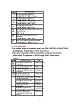
9.3. Symbolic Marks
The symbolic marks for resistors and capacitors which used in this circuits are classified as
following
Table-1
and
Table-2
.
9.3.1. RESISTORS
- Resistors without symbolic mark are FIXED CARBON FILM
RESISTORS (ERD-type).
- All resistors are 1/4 WATT, ±5 % TOLERANCE unless otherwise
designated in schematic diagrams.
Table-1
20
Содержание SX-KN2600EB
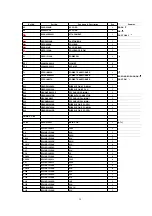
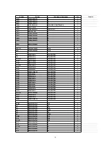
Страница 22: ...SYMBOL SPECIFICATION TYPE Multilayer Ceramic Chip Capacitors ECUV_type 10 MEASURING CONDITION 22 ...
Страница 27: ...A3 QJAG027AB AC CORD 1 EX EG EH EQ GU GT GM 27 ...
Страница 40: ...R625 ERDS2TJ124T 120K 1 40 ...
Страница 42: ...R691 92 ERDS2TJ223T 22K 2 42 ...
Страница 46: ...Ref No Part No Part Name Description Pcs Remarks 16 Cabinet Parts Location 46 ...
Страница 47: ...17 Control Panel Parts Location 47 ...
Страница 48: ...18 Packaging 48 ...
Страница 49: ...19 Schematic Diagram for printing with A4 S030500000 HM AM 49 ...