background image

-57-

Cette caméra couleur CCTV est un appareil de
vidéosurveillance qui incorpore un dispositif à transfert de
charge CCD de 1/4 de pouce, un zoom grossissant 30x,
préréglée et des capacités de balayage panoramique et
de réglage d’inclinaison dans une configuration en dôme.
Cet appareil offre également les caractéristiques
suivantes. 

Super Dynamic 

3

3

(SUPER-D 

3

3

)

Le processeur SUPER-D 

3

rend possible la capture

d’images claires de sujets diversement éclairés (page 77). 

Nouveau DSP pour une haute sensibilité

Un nouveau système de réduction de bruit réduit la
luminance minimum à 0,5 lux{fc} en mode couleur et à
0,04 en mode noir et blanc. 

Passage automatique de nuit en mode
Noir et blanc 

Cette caméra peut être configurée de manière à passer
automatiquement en mode noir et blanc dans des
conditions de faible lumière pour obtenir des images
claires même de nuit. 

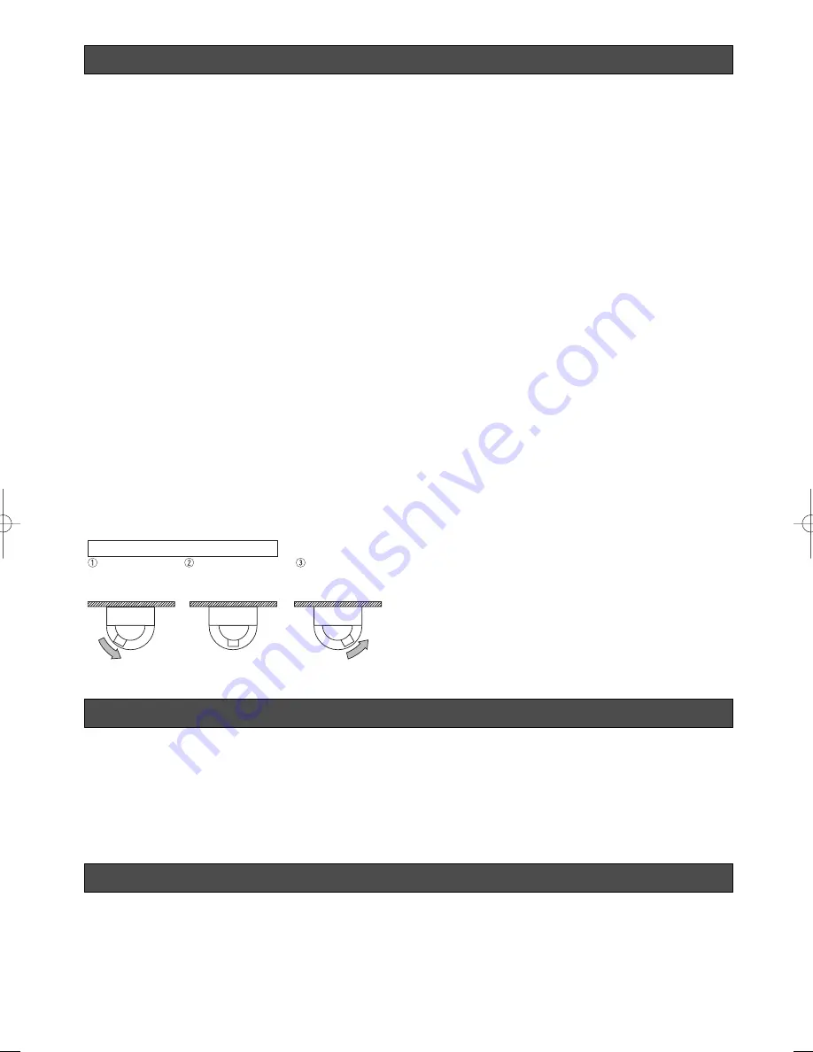
Digital Flip (retournement numérique)

Une caméra doit normalement s’arrêter pour pointer vers
le bas pendant une opération de retournement. Avec le
retournement numérique, la caméra peut s’incliner de 0 à
180 ° d’un seul mouvement. Il devient ainsi possible de
suivre sans problème des sujets passant directement sous
la caméra 

Fonction Zone de confidentialité

La fonction Zone de confidentialité permet de masquer
des zones spécifiques de manière qu’elles n’apparaissent
pas. 

Fonction Patrouille

La fonction patrouille garde en mémoire les mouvements
de routine manuels de la caméra pour pouvoir les relire en
cas de nécessité. Vous pouvez ainsi apprendre à la
caméra les mouvements des personnes à surveiller, en
relisant les paramètres mis en mémoire, les mouvements
automatiques sont faits automatiquement. 

Mémoire de position caméra

Le système peut être configuré avec 256 positions caméra
au maximum. Une position caméra particulière peut être
sélectionné et vue en saisissant le numéro de préréglée
applicable sur le clavier à 10 touches. 

Détection de mouvement

Le système peut être configuré de sorte que le moindre
mouvement sur l’écran de surveillance déclenche
l’émission d’un signal d’alarme. 
Cette fonction peut être utilisée avec un système de
magnétoscope pour enregistrer des images d'intrusion
nocturne. 

DÉNI DE LA GARANTIECARACTÉRISTIQUES

ACCESSOIRES

Mode d’emploi (ce manuel)  . . . . . . . . . . . . . . . . . . . . .1 él
Certificat de garantie  . . . . . . . . . . . . . . . . . . . . . . . . . .1 él

Les éléments suivants sont nécessaires à l’installation.
Couvercle décoratif  . . . . . . . . . . . . . . . . . . . . . . . . . . .1 él
Feuille de protection contre la poussière  . . . . . . . . . . .1 él
Câble d’alarme 8P  . . . . . . . . . . . . . . . . . . . . . . . . . . . .1 él
Câble d’alarme 4P  . . . . . . . . . . . . . . . . . . . . . . . . . . . .1 él
Connecteur pour 24 V CA  . . . . . . . . . . . . . . . . . . . . . .1 él


Fonctionnement de la bascule numérique

Inclinaison vers 
le bas

L’image se retourne 
lorsque la caméra est 
pointée vers le bas 
(environ 135

°

).

Inclinaison vers 
le haut.

. . . La bascule numérique est effectuée uniquement lorsque la manette de 

contrôle est tenue vers le bas. 

ACCESSOIRES EN OPTION

Couvercle de dôme (transparent à environ 50 %, type fumé)  . . . . .WV-CS3S
Support de montage plafond . . . . . . . . . . . . . . . . . . . . . . . . . . . . . . .WV-Q105/WV-Q116/WV-Q117
Support de montage mural  . . . . . . . . . . . . . . . . . . . . . . . . . . . . . . . .WV-Q118

 WV-CS954̲FR  09.1.21  2:55 PM  ページ57

Содержание Super Dynamic III WV-CS954

Страница 1: ...lor CCTV Camera Operating Instructions Model No WV CS954 Before attempting to connect or operate this product please read these instructions carefully and save this manual for future use FRANÇAIS ENGLISH ...

Страница 2: ...cause harmful interference to radio communications Operation of this equipment in a residential area is likely to cause harmful interference in which case the user will be required to correct the interference at his own expense FCC Caution To assure continued compliance example use only shielded interface cables when connecting to computer or peripheral devices Any changes or modifi cations not ex...

Страница 3: ...your outlet consult an electrician for replacement of the obsolete outlet 10 Protect the power cord from being walked on or pinched particularly at plugs convenience receptacles and the point where they exit from the apparatus 11 Only use attachments accessories specified by the manufacturer 12 Use only with the cart stand tripod bracket or table specified by the manufacturer or sold with the appa...

Страница 4: ...BY THE USER 4 INCONVENIENCE OR ANY LOSS ARISING WHEN IMAGES ARE NOT DISPLAYED DUE TO ANY REASON OR CAUSE INCLUDING ANY FAILURE OR PROBLEM OF THE PRODUCT THIS PUBLICATION COULD INCLUDE TECHNICAL INACCURACIES OR TYPOGRAPHICAL ERRORS CHANGES ARE ADDED TO THE INFORMATION HEREIN AT ANY TIME FOR THE IMPROVEMENTS OF THIS PUBLICATION AND OR THE CORRESPONDING PRODUCT S DISCLAIMER OF WARRANTY 5 ANY PROBLEM ...

Страница 5: ...n remembers manual camera move ment routines for automatic playback when they are needed For example you can teach the camera the movements of the people you want to monitor by replaying the stored parameters complicated move ments are done automatically Camera Position Memory The system can be configured with up to 256 camera positions A particular camera position can be selected and viewed by en...

Страница 6: ...nction 8 Do not operate the camera beyond the specified temperature humidity or power source ratings Do not use the camera in an extreme environment where high temperature or high humidity exists Do not place the camera near heat sources such as radiators stoves or other units that produce heat Use the camera under conditions where tempera ture is between 10 C 50 C 14 F 122 F preferably 40 C 104 F...

Страница 7: ...ra position is changed from a fixed position the discoloration at the previous location of the concentrated light will remain on the screen Do not point the camera at a strong light source Intense light such as that produced by a spotlight concentrated on one part of the screen can cause blooming rainbow around the strong light or smearing vertical stripes above and below the strong light Do not a...

Страница 8: ...or uploading downloaded data to the camera Uploading of WV CS954 preset data to other models e g WV CS854 WV CS854A WV CS854B and WV NS324 may cause an error and failure of the uploading process Self diagnosing Function If abnormal operation due to external noise or some other reason continues for more than 30 seconds the camera will automatically reset itself and restore normal operation Reset op...

Страница 9: ...1 14 CAMERA INSTALLATION 15 Preparing the Camera and Decorative Cover for Side Cable Exit 15 Installing the Camera 15 UNINSTALLING THE CAMERA 17 Removing the Decorative Cover 17 Uninstalling the Camera 17 CONNECTIONS 18 RS485 SETUP 20 USING THE SETUP MENU 21 Displaying the Setup Menu 21 Camera ID Settings 21 Scene Select Settings 22 Preset Position Settings 22 Language Setting 24 Advanced Menu Set...

Страница 10: ...has reached the end of its service life Contact a qualified service person or system installer to have it replaced Power Connector for Camera Video Output Connector Decorative Cover provided Dome Fix Ring Safety Wire Lens The lens cannot be replaced Data Port Alarm Output Connector Alarm Input Connector Camera Mounting Base Dome Cover Remove the camera first before removing the dome cover page 17 ...

Страница 11: ...ts of steam vapor and oil in flammable atmospheres other special environments Areas where radiation X rays strong electric waves or magnetism is generated At sea in coastal areas or in areas where corrosive gas is being generated Areas outside of the allowable ambient operating temperature range 10 C to 50 C 14 F to 122 F In a motor vehicle on a boat or other areas subject to strong vibration This...

Страница 12: ...TCH SETTINGS In a configuration where the camera s RS485 data port is used for camera control pan tilt etc by the system controller the camera s DIP switches must be configured to specify the unit number and communication parameters The camera mounting base needs to be removed to access the DIP switches See steps 1 and 2 on page 15 for information about how to remove the camera mounting base 1 2 3...

Страница 13: ...DIP Switch 1 Unit Number DIP Switch 1 Unit Number 1 96 1 2 3 4 5 6 7 8 9 10 11 12 13 14 15 16 17 18 19 20 21 22 23 24 25 26 27 28 29 30 31 32 33 34 35 36 37 38 39 40 41 42 43 44 45 46 47 48 49 50 51 52 53 54 55 56 57 58 59 60 61 62 63 64 65 66 67 68 1 2 3 4 ON 5 6 7 8 1 2 3 4 ON 5 6 7 8 1 2 3 4 ON 5 6 7 8 1 2 3 4 ON 5 6 7 8 1 2 3 4 ON 5 6 7 8 1 2 3 4 ON 5 6 7 8 1 2 3 4 ON 5 6 7 8 1 2 3 4 ON 5 6 7 ...

Страница 14: ...N 5 6 7 8 1 2 3 4 ON 5 6 7 8 1 2 3 4 ON 5 6 7 8 1 2 3 4 ON 5 6 7 8 1 2 3 4 ON 5 6 7 8 1 2 3 4 ON 5 6 7 8 1 2 3 4 ON 5 6 7 8 RS485 Communication Parameters DIP Switch 1 Configuring DIP Switch 1 as shown below resets communication parameters to their factory default settings You can then change the settings as desired 1 2 3 4 ON 5 6 7 8 DIP Switch 1 Setting Description 1 2 3 4 ON 5 6 7 8 1 2 3 4 ON ...

Страница 15: ...th it 1 Remove the fixing screw M3 6 that secures the camera to the camera mounting base Put the screw in a place where it will not become lost 2 Rotate the camera mounting base unit in the direction indicated by the arrow and remove it 3 Using the camera mounting base as a template mark the locations of the four mounting holes on the ceiling If you are using the top cable exit configuration mark ...

Страница 16: ...decorative cover comes with camera Press upwards on the decorative cover at the points marked indicated by the arrows in the illustration below to unhook the two parts from each other When removing the decorative cover the direction to press is shown on the side of the decorative cover Caution Pressing up on the wrong side of the decorative cover can damage it 10 Put the two pieces of the decorati...

Страница 17: ...ive cover the direction to press is shown on the side of the decorative cover Uninstalling the Camera The camera and its base unit are secured by screws This configuration provides double anchoring and you should use the following procedure to uninstall the camera 1 Remove the fixing screw that secures the camera to the camera mounting base Put the screw in a place where it will not become lost 2 ...

Страница 18: ... length of coaxial cable under 1200 meters in the case of 5C 2V 3 Be sure to connect the grounding cable to ground Alarm In Out Ratings Alarm In 5 V DC pull up input Drive capacity of at lease 0 2 mA required OFF 4 V DC minimum 5 V DC maximum or open ON 1 V DC maximum or short Alarm Out Open collector output 16 V DC 100 mA maximum drive capacity OFF Open ON 100 mA maximum When connecting to an ext...

Страница 19: ... individual conductors Prepare the individual conductors for clamping Use MOLEX band tool part number 57027 5000 for UL Style Cable UL1015 or 57026 5000 for UL Style UL1007 for clamping the contacts After clamping the contacts push them into the proper holes in the accessory connector of this camera until they snap in place Cautions Shrinking the cable entry seal is a one time procedure Do not shr...

Страница 20: ...1 7 Move the cursor to XON XOFF and then tilt the joystick left or right to select an XON XOFF setting The factory default setting is NOT USE NOT USE Disables X ON X OFF data flow control USE Enables X ON X OFF data flow control 8 Move the cursor to WAIT TIME and then tilt the joystick left or right to select a wait time setting The wait time is the time that the camera should wait before resendin...

Страница 21: ...ra ID display on and off 2 Select ON or OFF and then press the CAM SET button The factory default setting is OFF 3 Use the joystick to move the cursor the character you want to input and then press the CAM SET button This will cause the selected character to appear in the camera ID input area Repeat step 3 as many times as necessary to input all of the characters for the camera ID Example DOOR To ...

Страница 22: ...then press the CAM SET button This registers the position number setting and displays the preset setting menu this page To select a position number in the range of 033 to 064 move the cursor to 33 64 in the lower left corner of the menu and then press the CAM SET button Preset numbers set subsequently are the same Notes An asterisk to the right of a position number indicates that it already has a ...

Страница 23: ...ng information that has been downloaded saved before some unforeseen damage or malfunction causes setting information in the camera to be lost However there may be some slight differences in images from those uploaded recovered when the camera is changed The PAN OFFSET SET function is for adjusting these differences 1 Align the cursor with PAN OFFSET SET with the or arrow and press the CAM SET but...

Страница 24: ... been changed Do not operate the system controller when changing settings If you have selected either Japanese or Chinese as the language only the IDs and titles can be set in katakana or Chinese The LANGUAGE display remains in English even when the language setting is changed Advanced Menu Settings The advanced setup menu can be displayed from the setup menu 1 Display the setup menu page 21 move ...

Страница 25: ...righter area to become washed out SUPER D 3 digitally combines an image that is set up for a clear view of bright areas with an image that is set up for a clear view of dark areas creating a final image that preserves overall detail Notes SUPER D 3 is supported only when ALC is selected for light control ALC MANUAL Camera settings are limited to the following when SUPER D 3 is turned on SHUTTER OF...

Страница 26: ... shutter setting fluorescent lighting may cause flickering of the picture If this happens select OFF or 1 100 for the shutter speed setting AUTO is disabled when MANUAL is selected for light control ALC MANUAL and FIX is selected for electronic sensitivity enhancement SENS UP 4 Gain Control AGC 1 Move the cursor to AGC and then tilt the joystick left or right to select a gain control setting ON LO...

Страница 27: ...to zero crossing of the AC line phase If the AC line phase contains spike noise etc the vertical phase of the video output signal may be disturbed 7 White Balance WHITE BAL 1 Move the cursor to WHITE BAL and then tilt the joystick left or right to select a white balance mode 1 Auto Tracing White Balance Mode ATW1 ATW2 In this mode the camera continually monitors the color temperature of the light ...

Страница 28: ...t the joystick left to select the threshold illuminance level for switching between the color mode and the black and white mode The illuminance shown below is based on the assumption that the camera is used in an area lit by halogen lamps and that AGC on the menu is set to MID LOW Switches to the black and white mode when illuminance around the camera is approximately 1 5 lux fc or lower when AGC ...

Страница 29: ...ing manual operation zoom operation cannot go beyond the zoom limit Optical zoom ranges from 1 to 30 magnifications while digital zoom is used for higher magnifications up to 300 The factory default setting is x30 30x optical zoom Notes If zoom limit is set to more than 30x then zoom operation pauses at 30x magnification Increasing the zoom to over 30x magnification digital zoom decreases the reso...

Страница 30: ... in the range of 033 to 064 move the cursor to 33 64 in the lower left corner of the menu and then press the CAM SET button Preset numbers set subsequently are the same Notes An asterisk to the right of a position number indicates that it already has a preset position assigned to it The home position number is indicated by the letter H next to the asterisk When the cursor is located at a position ...

Страница 31: ...t the number of the scene file whose settings you want to configure 2 Press the CAM SET button This will display the scene file setting menu The following items can be set on the Scene file settings menu See camera settings for details on each setting SHUTTER page 26 AGC page 26 SENS UP page 26 WHITE BAL pages 27 28 MOTION DET page 38 Preset Speed Setting PRESET SPEED Set the speed the camera move...

Страница 32: ... shown below 3 Home Position Setting HOME POSITION A currently configured preset position can be designated as the home position Pressing the HOME button of the system controller will cause the camera to move to the currently specified home position Use the following procedure to make a preset position the home position 1 Move the cursor to HOME POSITION and then tilt the joystick left or right to...

Страница 33: ... ZOOM FOCUS is performed if AUTO PAN is operating and PAN TILT does SEQ SORT PATROL or AUTO TRACK movement Note however that that the contents of the setting menu do not change To return to the auto mode open the setup menu and then close it again The auto mode will also activate when the self return trigger time page 32 elapses During operation the lens may enter the refresh mode PATROL1 4 displa...

Страница 34: ... PATROL The patrol function remembers manual operations for later automatic playback when they are needed 1 Aim the camera with the menu closed at the start point of the routine you want it to remember 2 Move the cursor to NUMBER and then tilt the joystick left or right to specify the number of patrol routines Tilting the joystick cycles through settings in the sequence shown below The amount of s...

Страница 35: ...pecific areas of the scene screen from view Up to eight privacy zones can be configured Notes Certain camera orientations can cause privacy zone masked area to become visible The privacy zone function does not mask scene areas during the initialization routine performed immediately after camera power is turned on The zone position may shift if the stabilizer settings are change after setting the p...

Страница 36: ...o 12 Area Title Setting AREA TITLE The area title function lets you display a direction indicator that appears in the picture to indicate the direction of the location being shown on the screen Text can also be displayed in place of the direction indicators if desired The direction indicators are N north NE northeast E east SE southeast S south SW southwest W west and NW northwest 1 Move the curso...

Страница 37: ... to select an area title display position and then press the MON ESC button This registers the area title display position and returns to the area title NESW setting menu Note The area title is always displayed under the camera ID If you specify different display position settings for the camera ID and the area title ID the area title ID display position setting is used for both 2 When ON USER is ...

Страница 38: ...ask the areas of the screen that you do not want the motion detector to monitor for movement To mask screen areas use the same procedure as step 5 under SUPER D 3 Super Dynamic 3 on page 25 After configuring mask settings press the MON ESC button to return to the motion detector setting menu 3 Move the cursor to ALARM and then tilt the joystick left or right to toggle demo mode see step 5 alarm ou...

Страница 39: ...he preset alarm will output an alarm from the video output port or alarm output connector when the camera completes a move to a preset position An alarm is output in the following cases When the self return function is activated page 32 and the camera finishes moving to the home position and when switching to the auto mode When SEQ is selected for the auto mode page 32 and the camera completes a m...

Страница 40: ...ed to the camera settings and are kept even after the camera is turned on again PATROL1 S 4 S displays only the set number of patrol routines page 34 6 Move the cursor to CNT CLS 1 and then tilt the joystick left and right to select the alarm output that should be performed over ALARM OUT 1 when an alarm is detected OFF No alarm output ALARM Output an alarm signal when an alarm is detected by the ...

Страница 41: ...ays for the alarm display are shown in the table below Notes Use a shortcut page 47 to switch between displaying or not displaying the pan tilt zoom positions during pan tilt and zoom operation and type of alarm on the monitor screen The tilt position is displayed ranging from 5 to 90 to 5 When the Light Control is in ALC IRIS CLOSE is displayed below the pan tilt zoom position display when the ir...

Страница 42: ...FRESH and then press the F3 button The refresh function corrects the camera position when it starts to deviate from the preset positions 5 Returning Camera Settings to Their Defaults CAMERA RESET 1 To reset the camera to its initial default settings move the cursor to PUSH SET to the right of CAMERA RESET and then press the F4 button This resets the camera to it initial factory default settings No...

Страница 43: ...e select settings First display the scene select setting menu 1 Display the setup menu page 21 move the cursor to SCENE SELECT O and then press the CAM SET button This will display the scene select setting menu Scene Select Settings See page 22 for information on the scene select settings method SCENE SELECT SCENE INDOOR L LOAD RET TOP ...

Страница 44: ...e factory default password is 123 4 Press the CAM SET button This returns to the setup menu and toggles PASSWORD LOCK on or off The password input screen will reappear if you press the CAM SET button after inputting the wrong password If this happens perform step 3 again Changing the Password After turning on password lock it is recommended that you use the following procedure to change the factor...

Страница 45: ...creen again for verification Note that you cannot register the new password by pressing the MON ESC button 6 Input the new 3 digit password again by moving the cursor to each of the applicable numbers along the top of the screen 0 to 9 and pressing the CAM SET button for each digit After you input all three digits move the cursor to OK 7 Press the CAM SET button This completes the password change ...

Страница 46: ...UTO PAN speed one step 6 8 CAM FUNCTION Decreases AUTO PAN speed one step 6 9 CAM FUNCTION Sets AUTO PAN start point 7 0 CAM FUNCTION Sets AUTO PAN end point 7 1 CAM FUNCTION AUTO MODE OFF 7 2 CAM FUNCTION AUTO MODE SEQ ON 7 3 CAM FUNCTION AUTO MODE SORT ON 7 4 CAM FUNCTION Reverses AUTO PAN range 7 6 CAM FUNCTION ENDLESS ON 7 7 CAM FUNCTION ENDLESS OFF 7 8 CAM FUNCTION DIGITAL FLIP ON 7 9 CAM FUN...

Страница 47: ...AM FUNCTION BW AUTO switching time 10 seconds 1 9 1 CAM FUNCTION BW AUTO switching time 30 seconds 1 9 2 CAM FUNCTION BW AUTO switching time 60 seconds 1 9 3 CAM FUNCTION BW AUTO switching time 300 seconds 1 9 4 CAM FUNCTION PATROL2 PLAY 1 9 5 CAM FUNCTION PATROL3 PLAY 1 9 6 CAM FUNCTION PATROL4 PLAY 1 9 7 CAM FUNCTION PATROL2 LEARN start 1 9 8 CAM FUNCTION PATROL3 LEARN start 1 9 9 CAM FUNCTION P...

Страница 48: ... with your system controller Is the lens iris closed Execute the iris reset from the system controller you are using 25 26 Is the camera set up for a fixed shutter speed 26 White picture Is FIX selected for the electronic sensitivity enhancement SENS UP setting 26 Is the lens iris open 25 26 Out of focus picture Is the dome cover or lens of the camera dirty If so clean them 7 Is the object one tha...

Страница 49: ...ion Check the setting of this mode 28 Frequent switching between the color and the black and white modes Adjust the black and white mode switching level and the duration time setting 28 White specks in the picture Use the PIX OFF function to perform blemish compensation 41 42 Menu does not open Is the camera connected correctly See the operating instructions that come with the system controller yo...

Страница 50: ... camera connected correctly See the operating instructions that come with the system controller you are using The camera has a pan limit function Check the PAN LIMIT settings 33 The motor or lens may be worn Contact a quality service person or system installer Problem Cause and Recommended Action Reference Pages The camera movement modes OFF SEQ SORT AUTO PAN PATROL AUTO TRACK do not work Check th...

Страница 51: ... return function 32 Problem Cause and Recommended Action Reference Pages Camera position is different from the preset position setting Perform REFRESH from the special setup menu 42 Picture is different from the position setting Adjust the picture using the preset menu and a scene file 30 31 Upper part of the picture is black when the camera is in a horizontal orientation This is caused by the cam...

Страница 52: ... Humidity 90 max non condensation Dimensions 154 5 mm D 233 mm H 6 5 64 D 9 11 64 H Weight Approximately 2 2 kg 4 9 lbs Finish Camera Die cast aluminum with baked melanin coating Paint color Fine silver Dome Clear acrylic resin Pan and Tilt Panning Range 360 endless Panning Modes Manual auto manual position sequential position Panning Speed Manual Approximately 0 065 s to 120 s 8 steps 16 steps 64...

Страница 53: ...level MANUAL Shutter OFF 1 60 AUTO 1 100 1 250 1 500 1 1000 1 2000 1 4000 1 10000 Electronic Sensitivity Enhancement 32X max AUTO or FIX Auto Mode OFF SEQ SORT AUTO PAN PATROL AUTO TRACK Auto Pan Key SEQ SORT AUTO PAN PATROL AUTO TRACK Digital Flip ON OFF SUPER D3 ON OFF Motion Detector OFF MODE1 MODE2 Alarm Input Output 4 inputs ALARM IN 1 to ALARM IN 4 2 outputs ALARM AUX1 BW AUX2 Black and Whit...

Страница 54: ... triangle équilatéral sert à attirer l atten tion de l utilisateur sur des instructions de fonctionnement et d entretien de dépannage à caractère important dans la brochure qui accompagne l ap pareil Le numéro de série de l appareil se trouve sur la plaque supérieure Nous vous conseillons de relever le numéro de série de votre appareil dans l espace réservé ci dessous et de conserver précieusement...

Страница 55: ...illez consulter un électricien pour qu il effectue le remplacement de l ancienne prise de sortie secteur 10 Protéger le cordon d alimentation afin que personne ne marche dessus et que le cordon ne soit pas pincé notamment au niveau des prises des prises pratiques et du point de sortie de l appareil 11 Utiliser uniquement les fixations ou les accessoires spécifiés par le fabricant 12 Utiliser uniqu...

Страница 56: ...PRODUIT 2 BLESSURE PERSONNELLE OU TOUT DÉGÂT CAUSÉS PAR UN USAGE NON APPROPRIÉ OU UNE UTILISA TION NÉGLIGENTE DE L UTILISATEUR 3 DÉMONTAGE RÉPARATION OU MODIFICATION NON AUTORISÉS DU PRODUIT EFFECTUÉS PAR L UTILISA TEUR 4 LES INCONVÉNIENTS OU PERTES QUI SURVIEN NENT SI LES IMAGES NE SONT PAS AFFICHÉES DU FAIT D UNE QUELCONQUE RAISON OU CAUSE INCLUANT UNE QUELCONQUE PANNE OU PROBLÈME INHÉRENT AU PR...

Страница 57: ...La fonction patrouille garde en mémoire les mouvements de routine manuels de la caméra pour pouvoir les relire en cas de nécessité Vous pouvez ainsi apprendre à la caméra les mouvements des personnes à surveiller en relisant les paramètres mis en mémoire les mouvements automatiques sont faits automatiquement Mémoire de position caméra Le système peut être configuré avec 256 positions caméra au max...

Страница 58: ...amais faire fonctionner la caméra dans des con ditions excédant ses limites d utilisation en termes de température d humidité ou de puissance d ali mentation Evitez d utiliser la caméra dans un milieu extrême avec des conditions de température ou d humidité très élevées La caméra ne doit pas être placée près de sources de chaleur telles que des radiateurs des poêles ou tout autre appareil produisa...

Страница 59: ...îner une détérioration du filtre couleur intégré dans le dispositif à transfert de charge CCD et une décoloration de la partie affectée Même si la position de la caméra vidéo est modifiée la décoloration persiste à l endroit où la lumière s était concentrée Ne pas pointer la caméra en direction d une source lumineuse violente Une lumière intense comme celle d un projecteur concentré sur un endroit...

Страница 60: ... de télécharger ces données vers la caméra Le téléchargement des données de préréglage du WV CS954 vers d autres modèles par exemple WV CS854 WV CS854A WV CS854B et WV NS324 peut entraîner des erreurs ou l échec du processus de téléchargement Fonction d auto diagnostic Si un dysfonctionnement dû à un bruit externe ou à tout autre raison se prolonge au delà de 30 secondes la caméra se réinitialise ...

Страница 61: ... la caméra et du couvercle décoratif pour une sortie latérale du câble 67 Installation de la caméra vidéo 67 ENLEVER LA CAMÉRA 69 Retrait du couvercle décoratif 69 Enlever la caméra vidéo 69 BRANCHEMENTS 70 RS485 AJUST 72 UTILISATION DU MENU DE CONFIGURATION 73 Affichage du menu de configuration 73 Réglages de l identifiant de la caméra vidéo 73 Réglages de la sélection de scènes 73 Réglages des p...

Страница 62: ...mandez à un technicien ou à l installateur système qualifiés de la remplacer L objectif ne peut pas être remplacé Connecteur d entrée d alarme Connecteur de sortie d alarme Connecteur de sortie vidéo Port de transmission de données Câble d alimentation de la caméra Base de fixation de la caméra Fil de sécurité Couvercle décoratif fourni Bague de fixation du dôme Caméra Couvercle du dôme Retirez d ...

Страница 63: ... un véhicule à moteur un bateau ou dans d autres lieux soumis à de fortes vibrations cette caméra vidéo n est pas destinée à une utilisation à bord d un véhicule A proximité d une bouche d aération d une porte qui s ouvre vers l extérieur ou tout autre endroit sujet à des températures extrêmes de telles conditions provoquent la formation de buée et de condensation sur le couvercle du dôme Les câbl...

Страница 64: ...mètres de communication La base de fixation de la caméra doit être retirée pour accéder aux interrupteurs DIP Voir les étapes 1 et 2 à la page 67 pour des informations sur la manière de démonter la base de fixation de la caméra 1 2 3 4 1 2 3 4 ON OUI ON OUI 5 6 7 8 Interrupteur DIP 1 Interrupteur DIP 2 Paramètres de communications Interrupteur DIP 2 Le réglage d usine par défaut de ces interrupteu...

Страница 65: ...2 53 54 55 56 57 58 59 60 61 62 63 64 65 66 67 68 1 2 3 4 5 6 7 8 1 2 3 4 5 6 7 8 1 2 3 4 5 6 7 8 1 2 3 4 5 6 7 8 1 2 3 4 5 6 7 8 1 2 3 4 5 6 7 8 1 2 3 4 5 6 7 8 1 2 3 4 5 6 7 8 1 2 3 4 5 6 7 8 1 2 3 4 5 6 7 8 1 2 3 4 5 6 7 8 1 2 3 4 5 6 7 8 1 2 3 4 5 6 7 8 1 2 3 4 5 6 7 8 1 2 3 4 5 6 7 8 1 2 3 4 5 6 8 1 2 3 4 5 6 7 8 1 2 3 4 5 6 7 8 1 2 3 4 5 6 7 8 1 2 3 4 5 6 8 1 2 3 4 5 6 7 8 1 2 3 4 5 6 7 8 1 ...

Страница 66: ...N OUI ON OUI ON OUI ON OUI ON OUI ON OUI ON OUI ON OUI ON OUI ON OUI ON OUI ON OUI ON OUI Paramètres de communication RS485 Interrupteur DIP 1 Le fait de configurer l interrupteur DIP 1 de la manière indiquée ci dessous réinitialise les paramètres de communication à leurs réglages par défaut d usine Vous pouvez changer ces réglages selon vos souhaits 1 2 3 4 5 6 7 8 Interrupteur DIP 1 Description ...

Страница 67: ...base de fixation de la caméra Mettez la vis de côté de manière à pouvoir la retrouver facilement 2 Faites pivoter la base de fixation de la caméra dans le sens indiqué par la flèche et retirez la 3 Utilisez la base de fixation de la caméra comme un gabarit pour repérer et marquer l emplacement des 4 points de fixation au plafond Si vous utilisez la configuration de sortie supérieure de câble marqu...

Страница 68: ...a Poussez le couvercle décoratif vers le haut en appuyant sur les points indiqués repérés par les flèches dans l illustration ci dessous pour déboîter les deux parties l une de l autre Pour enlever le couvercle décoratif la direction à presser est indiquée sur le côté du couvercle Attention Si vous appuyez sur le mauvais côté du couvercle décoratif vous risquez de l endommager 10 Placez les deux p...

Страница 69: ...n à appuyer est indiquée sur le côté du couvercle Enlever la caméra vidéo La caméra vidéo et sa base sont fixées par des vis Cela fournit un double ancrage pour retirer la caméra vous devez suivre la procédure suivante 1 Retirez la vis qui maintient la caméra sur sa base de fixation de la caméra Mettez la vis de côté de manière à pouvoir la retrouver facilement 2 Retirez la caméra de sa base de fi...

Страница 70: ...1 200 mètres en cas de 5C 2V 3 Assurez vous de connecter le câble conducteur de terre à la terre Capacités entrée sortie d alarme Entrée d alarme Entrée amplifiée 5 V CC Capacité d excitation requise d au moins 0 2 mA OFF 4 V CC minimum 5 V CC maximum ou ouvert OUI 1 V CC maximum or court circuit Sortie d alarme Sortie collecteur ouvert 16 V CC capacité d excitation maximum 100 mA OFF Ouvert OUI 1...

Страница 71: ...hé Utilisez l outil de fixation MOLEX numéro 57027 5000 pour un câble de type UL UL1015 ou 57026 5000 pour un câble de type UL UL1007 pour attacher les broches de contact Après avoir fixé les contacts repoussez les dans les trous adéquats du connecteur d accessoires de cette caméra jusqu à leur mise en place Attention Rétrécir la gaine d entrée de câble ne s effectue qu une seule fois Ne pas la ré...

Страница 72: ...manette de réglage tous azimuts à gauche ou à droite pour sélectionner réglage de bit d arrêt 1 ou 2 Le réglage d usine par défaut est 1 7 Amenez le curseur sur XON XOFF puis inclinez la manette de réglage tous azimuts à gauche ou à droite pour sélectionner un réglage XON XOFF Le réglage d usine par défaut est NON UTILE NON UTILE Désactive le contrôle de flux de données X ON X OFF UTILISE Active l...

Страница 73: ...de la manette de réglage tous azimuts pour amenez le curseur sur le caractère souhaité et appuyez ensuite sur le bouton CAM SET Le caractère sélectionné apparaît alors dans la zone de saisie d ID de caméra Répétez l étape 3 autant de fois qu il le faut pour saisir tous les caractères de l ID de caméra Exemple DOOR Pour saisir un espace Amenez le curseur sur ESPACE et appuyez ensuite sur le bouton ...

Страница 74: ... les rapports avec les autres réglages sont montrés dans le tableau ci dessous 2 Amenez le curseur sur CHARGEMENT et appuyez ensuite sur le bouton CAM SET Ceci a pour effet d appliquer à l image la configuration que vous avez sélectionnée pour SCENE à l étape 1 Réglages des positions définies au préalable Sélection du numéro de position TABLE Pour sélectionner un numéro de position vous pouvez uti...

Страница 75: ...ton CAM SET pour afficher le menu de réglage de ZOOM FOCUS 5 Déplacez la manette de réglage à gauche à droite en haut et en bas pour ajuster la position de la mise au point et appuyez ensuite sur le bouton CAM SET Remarques La mise au point peut s avérer difficile lorsque la caméra vidéo est à un angle proche de l horizontale en raison de la déformation créée par la courbe du couvercle du dôme Un ...

Страница 76: ... rapide Page 73 o MOT DE PASSE Réglage de mot de passe Page 96 Ce paramètre s affiche uniquement si les réglages de RS485 sont configurés avec les interrupteurs DIP 76 MODELE WV CS954 CAMÉRA PAN AZIMUTH ALARME SPECIAL COMMUNICATION SELECT SCENE LANGUAGE AJUST RAPIDE MOT DE PASSE OFF q e t u o w r y i Réglage de langue 1 Amenez le curseur sur LANGUAGE O et appuyez ensuite sur le bouton CAM SET 2 Su...

Страница 77: ...ajuste l objectif en fonction des zones lumineuses Il en résulte une perte de détails dans les zones sombres Au contraire l ajustement de la luminosité de l objectif en fonction des zones sombres fait que les zones lumineuses deviennent pâles SUPER D 3 combine numériquement une image configurée pour une vision nette des zones lumineuses avec une image configurée pour une vision nette des zones som...

Страница 78: ...déplacement automatique de l obturateur lorsque cela est nécessaire d obtenir une image plus claire d objets extrêmement lumineux en extérieur etc Il s agit du réglage par défaut OFF réglé sur 1 60 seconde Remarques Lorsqu AUTO est sélectionné pour le réglage de l obturateur la lumière fluorescente risque de provoquer des scintillements sur l image Si cela se produit sélectionnez OFF ou 1 100 pour...

Страница 79: ...R global et FIN précis à les valeurs préréglées appuyez sur le bouton F3 Pour WV RM70 appuyez simultanément sur les interrupteurs gauche et droit La position de la valeur de préréglage global GROSSIER correspond à l intersection à zéro avec la phase de ligne de courant alternatif Si la phase de ligne CA contient des crêtes de bruit etc la phase verticale du signal de sortie vidéo peut être perturb...

Страница 80: ... caméra est utilisée dans une zone éclairée par des lampes halogènes et que dans le menu CAG est réglé sur MOYEN BAS Commute le mode noir et blanc quand la luminosité autour de la caméra est à environ 1 5 lux fc ou moins quand CAG OUI MOYEN VISION NUIT OFF est réglé ÉLEVÉ Commute le mode noir et blanc quand la luminosité autour de la caméra est à environ 3 lux fc ou moins quand CAG OUI MOYEN VISIO...

Страница 81: ...périeurs jusqu à 300 Par défaut le réglage est x30 zoom optique x30 Remarques Si la limite zoom est réglée sur plus de 30x le grossissement maximal du zoom est de 30x Lorsque le zoom est réglé sur un grossissement de plus de 30x zoom numérique la résolution diminue Vous ne pouvez pas sélectionner un grossissement supérieur à 30x en guise de position prédéfinie 13 Stabilisateur d images automatique...

Страница 82: ...tte page Pour sélectionner un numéro de position dans la fourchette de 033 à 064 amenez le curseur sur 33 64 dans le coin inférieur gauche du menu puis appuyez sur le bouton CAM SET Les numéros préréglés configurés à la suite sont les mêmes Remarques Un astérisque à la droite d un numéro de position indique qu il a déjà une position préréglée qui lui a été assignée Le numéro de position d origine ...

Страница 83: ...seur sur FICHIER SCÉNE puis inclinez le à gauche ou à droite pour sélectionner le numéro de fichier de scène à configurer 2 Appuyez sur le bouton CAM SET Ceci permet d afficher le menu de configuration du fichier de scène Les paramètres suivants peuvent être réglés avec le menu de réglage de fichier de scène Voir les réglages de caméra pour des détails sur chaque réglage SHUTTER page 78 CAG page 7...

Страница 84: ... Réglage de position d origine POSI ORIGINE Une position préréglée en cours peut être désignée en tant que position d origine En appuyant sur le bouton HOME du contrôleur de système la caméra passe sur la position attribuée à la position d origine Utilisez la procédure suivante pour attributer à une position préréglée la position d origine 1 Amenez le curseur sur POSI ORIGINE puis inclinez la mane...

Страница 85: ...ué ci dessous Remarques Le mode automatique est automatiqement quitté lorsqu un PAN AZIMUTH ou un ZOOM FOCUS manuel est effectué alors qu AUTO PAN fonctionne et que PAN AZIMUTH effectue des mouvements SÉQ TRI PATR ou SUIVI AUTO Notez cependant que le contenu du menu de réglage ne change pas Pour retourner en mode automatique ouvrez le menu de configuration et fermez le à nouveau Le mode automatiqu...

Страница 86: ...ne écran de manière qu elles n apparaissent pas 8 zones de confidentialité au maximum peuvent être configurées 7 Réglage de la fonction de patrouille PATROUILLE La fonction patrouille garde en mémoire les opérations manuelles pour pouvoir les relire en cas de nécessité 1 Dirigez la caméra menu fermé sur le point de départ de la routine dont vous souhaitez vous rappeler 2 Amenez le curseur sur NUME...

Страница 87: ...nes orientations de la caméra peuvent rendre visibles des zones de confidentialité masquées La fonction de zone de confidentialité ne masque pas les zones pendant la routine d initialisation effectuée juste après la mise sous tension de la caméra La position de zone peut varier si les paramètres du stabilisateur sont modifiés après réglage de la zone de confidentialité 1 Amenez le curseur sur ZONE...

Страница 88: ...érique Avec ce réglage le rayon de retournement est de 0 à 90 Remarques Le retournement numérique est effectué uniquement lorsque la manette de réglage est tenue directement vers le bas Elle ne se fait pas si la manette de réglage est penchée sur une autre direction Lorsque OFF est sélectionné pour RETOURNEMENT les étapes suivantes doivent être effectuées pour pencher la caméra à 180 1 Basculez la...

Страница 89: ...ffichage du titre de zone est effectué et le menu de réglage de titre de zone NESO s affiche Remarque Le titre de zone est toujours affiché sous l ID de caméra Si vous définissez des réglages de position d affichage différents pour l ID de caméra et l ID de titre de zone le réglage de position de l affichage de l ID de titre de zone est utilisé pour les deux 2 Si OUI UTIL est sélectionné Après avo...

Страница 90: ...ci a pour effet d afficher l écran de réglage de masque 2 Masquez les zones de l écran pour lesquelles vous ne souhaitez pas de surveillance du détecteur de mouvement Pour masque des zones de l écran utilisez la même procédure qu à l étape 5 sous SUPER D 3 Super Dynamic 3 en page 77 Après avoir configuré les réglages de masque appuyez sur le bouton MON ESC pour revenir au menu de réglage du détect...

Страница 91: ...ument aucune responsabilité pour les accidents ou les pertes qui surviennent lors de l utilisation de ce produit 2 Configuration de préréglage d alarme ALARME PREPO Le fait d activer l alarme préréglée provoque l émission d une alarme depuis le port de sortie vidéo ou le connecteur de sortie d alarme lorsque la caméra atteint une position préréglée Une alarme est émise dans les cas suivants Lorsqu...

Страница 92: ...figurées page 86 6 Amenez le curseur sur CONTACT 1 puis inclinez la manette de réglage à gauche et à droite pour sélectionner la sortie d alarme qui doit être effectuée sur ALARM OUT 1 lorsqu une alarme est détectée OFF Aucune sortie d alarme ALARME Émettre un signal d alarme lorsqu une alarme est détectée par le détecteur de mouve ment page 90 ou l alarme préréglée page 91 Après avoir sélectionné...

Страница 93: ...s noms et types d écrans d alarme sont détaillés dans le tableau ci dessous Remarques Utiliser un raccourci page 99 pour afficher ou non sur l écran de surveillance des positions de balayage panoramique d inclinaison et de zoom lors du balayage de l inclinaison ou du zoom ainsi que le type d alarme La position d inclinaison comprise entre 5 et 90 est affichée Lorsque le contrôle de lumière est en ...

Страница 94: ...s positions préréglées 5 Restauration des réglages par défaut de la caméra vidéo RESET CAMERA 1 Pour réinitialiser la caméra à ses réglages par défaut d usine amenez le curseur sur BOUTON SET à droite de RESET CAMERA et appuyez sur le bouton F4 Ceci a pour effet de ramener la caméra à ses réglages par défaut d usine Noter cependant que cela ne modifie pas la position de la caméra vidéo définie au ...

Страница 95: ...ord le menu de réglage de sélection de scène 1 Affichez le menu de configuration voir page 73 amenez le curseur jusqu à SELECT SCENE O et appuyez ensuite sur le bouton CAM SET Ceci permet d afficher le menu de configuration de sélection de scène Réglages de sélection de scène Voir la page 73 pour plus d informations au sujet de la méthode de réglage de la sélection de scènes SELECT SCENE SCENE INT...

Страница 96: ...reur de saisie amenez le curseur sur RESET appuyez sur le bouton CAM SET et re saisissez tout le mot de passe Remarque Le mot de passe d usine par défaut est 123 4 Appuyez sur le bouton CAM SET Ceci a pour effet de retourner au menu de configuration et de basculer MOT DE PASSE sur OUI ou off L écran de saisie du mot de passe réapparaît si vous appuyez sur le bouton CAM SET après avoir saisi un mau...

Страница 97: ...de passe pour vérification Notez que vous ne pouvez pas enregistrer le nouveau mot de passe en appuyant sur la touche MON ESC 6 Saisissez à nouveau le nouveau mot de passe à trois chiffres en amenant le curseur sur chacun des chiffres appropriés sur le haut de l écran 0 à 9 et en pressant sur le bouton CAM SET pour chaque chiffre Après avoir saisi les trois chiffres amenez le curseur sur OK 7 Appu...

Страница 98: ...UI 6 6 CAM FUNCTION AUTO PAN OFF 6 7 CAM FUNCTION Augmente la vitesse d AUTO PAN d un pas 6 8 CAM FUNCTION Diminue la vitesse d AUTO PAN d un pas 6 9 CAM FUNCTION Règle le point de départ d AUTO PAN 7 0 CAM FUNCTION Règle le point de fin de course de AUTO PAN 7 1 CAM FUNCTION MODE AUTO OFF 7 2 CAM FUNCTION MODE AUTO SÉQ OUI 7 3 CAM FUNCTION MODE AUTO TRI OUI 7 4 CAM FUNCTION Inverse la portée d AU...

Страница 99: ...1 9 0 CAM FUNCTION Temps de basculement NB AUTO 10 secondes 1 9 1 CAM FUNCTION Temps de basculement NB AUTO 30 secondes 1 9 2 CAM FUNCTION Temps de basculement NB AUTO 60 secondes 1 9 3 CAM FUNCTION Temps de basculement NB AUTO 300 secondes 1 9 4 CAM FUNCTION PATR2 LECTURE 1 9 5 CAM FUNCTION PATR3 LECTURE 1 9 6 CAM FUNCTION PATR4 LECTURE 1 9 7 CAM FUNCTION PATR2 Début de MÉMORISATION 1 9 8 CAM FUN...

Страница 100: ...tialisation du diaphragme du contrôleur de système utilisé 77 78 La caméra est elle réglée sur une vitesse d obturation fixe 78 Image blanche FIXE est il sélectionné pour le réglage d accroissement de sensibilité électronique VISION NUIT 78 79 L objectif est il ouvert 77 78 Image floue Le couvercle du dôme ou l objectif est il sale Si oui nettoyez les 59 L objet est il incompatible avec la mise au...

Страница 101: ... couleur et noir et blanc Ajustez le niveau de commutation de mode noir et blanc et le réglage la durée du délai 80 Points blancs sur l image Utilisez la fonction PIX OFF pour effectuer une compensation d imperfection 93 94 Le menu n ouvre pas La camera est elle correctement branchée Voir le mode d emploi fourni avec le contrôleur de système que vous utilisez Est ce que des réglages de communicati...

Страница 102: ...elle correctement branchée Voir le mode d emploi fourni avec le contrôleur de système que vous utilisez La caméra a une fonction de limite de balayage panoramique Vérifier les réglages LIMIT PAN 85 Le moteur ou l objectif peuvent être usés Contactez un dépanneur ou un installateur système qualifiés Les modes de mouvement de la caméra OFF SÉQ TRI AUTO PAN PATROUILLE SUIVI AUTO ne fonctionnent pas V...

Страница 103: ...ge Vérifiez la fonction de retour automatique 84 La position de la caméra est différente de la position préréglée Faites RAFRAICHIR à partir du menu de réglage spécial 94 L image est différente par rapport au réglage de position Ajustez l image avec le menu préréglé et un fichier de scène 82 83 La partie supérieure de l image est noire lorsque la caméra est en orientation horizontale Cela vient du...

Страница 104: ...Dimensions 154 5 mm P 233 mm H 6 5 64 P 9 11 64 H Poids Environ 2 2 kg 4 9 lbs Finition Caméra video Aluminium moulé avec un revêtement de mélanine Couleur de peinture Argent fin Dôme Résine acrylique transparente Pan Azimuth Limite de balayage panoramique 360 infini Modes de balayage panoramique Manuel auto position manuelle position séquentielle Vitesse de balayage panoramique Manuel Environ 0 0...

Страница 105: ...urateur OFF 1 60 AUTO 1 100 1 250 1 500 1 1000 1 2000 1 4000 1 10000 Accroissement de la sensibilité électronique 32X max AUTO ou FIXE Mode automatique OFF SÉQ TRI AUTO PAN PATR SUIVI AUTO Touche balayage panoramique SÉQ TRI AUTO PAN PATR SUIVI AUTO Digital Flip retournement numérique OUI OFF SUPER D3 OUI OFF Détecteur de mouvement OFF MODE1 MODE2 Entrée sortie d alarme 4 entrées ALM IN 1 à ALM IN...

Страница 106: ... 106 ...

Страница 107: ... 107 ...

Страница 108: ...Printed in China As0109 1010 3TR003278HZA Imprimé en Chine ...

Отзывы: