background image

5

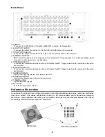
Back Panel

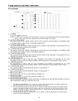
(13) INPUT

To connect to the MED probe, through the MED-CO3 connector, to the amplifier.

(14) OUTPUT(1-32CH)

To connect the output of channels 1-32 to the to the first A/D board in the computer.


(15) OUTPUT(33-64CH)

To connect the output of channels 33-64 to the to the second A/D board in the computer.

(16) SIGNAL OUTPUT

BNC connectors used to send analog outputs from selected recording channels to an external amplifier, signal
processor, or other device (e.g. - oscilloscope). 

(17) STIMULUS EXT 1

To connect to an external stimulus isolation unit. Outputs the EXT 1 trigger pulse from the computer to the exter-

nal stimulator.

(18) STIMULUS EXT 2

To connect to an external stimulus isolation unit. Outputs the EXT 2 trigger pulse from the computer to the exter-

nal stimulator.

(19) OPERATION IN

A port of input trigger signals from the external components.

(20) OPERATION OUT

A port of output trigger signals to the external components.

(21) SIGNAL GND

A ground terminal for signals.

(22) ~ AC IN

Insert the AC power supply cord here.

Reference Electrodes

To optimize the signals from all 64 electrodes as recording/stimulating electrodes, reference electrodes
have been added. This allows differential recording to be made between each channel and reference
electrodes. It also optimizes the delivery of mono-polar stimuli, as they are delivered between the chosen
(recording) electrode and the reference electrodes.

MED probe

Reference electrodes

Содержание SU-MED640P

Страница 1: ...64 CHANNEL INTEGRATED AMPLIFIER Operating Instructions P N SU MED640P Panasonic ...

Страница 2: ...a connection A DC power source can not be used Be sure to check the power source carefully Power cord protection Avoid using AC power cords with cuts scratches or poor connectors as this may result in fire or electric shock Excessive bending pulling or slicing of the cord should also be avoided Do not pull on the cord when you are disconnecting the power as this could cause an electric shock Grasp...

Страница 3: ...rtened Safety related symbols used on equipment and documentation Environmental conditions Indoor use Altitude up to 2000 m Temperature 5 40 C Maximum relative humidity 80 for temperatures up to 31 C decreasing linearly to 50 relative humidity at 40 C Mains supply voltage fluctuations not to exceed 10 of the nominal voltage Maintenance Clean the cabinet panel and controls with a soft cloth lightly...

Страница 4: ...LITUDE CH2 This potentiometer is used to adjust the output amplitude for the variable CH2 stimulator 4 The initial x1 amplitude which is set in the computer software can be adjusted in 0 1 steps between 0 and 10 times 8 OUTPUT EXT CH3 The output terminal for an external stimulus isolation unit see page 4 2 3 9 OUTPUT EXT CH4 The output terminal for an external stimulus isolation unit see page 4 2 ...

Страница 5: ... stimulator 18 STIMULUS EXT 2 To connect to an external stimulus isolation unit Outputs the EXT 2 trigger pulse from the computer to the exter nal stimulator 19 OPERATION IN A port of input trigger signals from the external components 20 OPERATION OUT A port of output trigger signals to the external components 21 SIGNAL GND A ground terminal for signals 22 AC IN Insert the AC power supply cord her...

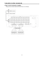
Страница 6: ...s Usage of internal stimulus amplifier Components and cables indicated with dashed lines are not included MED Connector A D board cables NI SH 100100 Connector cable included A D board in PC NI PCI 6071E A D board in PC NI PCI 6071E ...

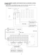
Страница 7: ...imulator outputs CH1 or CH2 Components and cables indicated with dashed lines are not included External Stimulator External Isolator External Stimulator External Isolator BNC cables BNC cables BNC cables A D board cables NI SH 100100 A D board in PC NI PCI 6071E A D board in PC NI PCI 6071E MED Connector Connector cable included Oscilloscope ...

Страница 8: ...e date original purchase in the event of a defect in materials or workmanship The product warranty covers failures due to defects in materials or workmanship which occur during nor mal use It does NOT cover damage which occurs in shipment or failures which are caused by products not supplied by AMS In addition this warranty does not cover failures resulting with results from alter ation accident m...

Страница 9: ...n 1000 times 1 mV V 60 dB Low cut filter PC control Stimulation 64 CH switch 4 mode 0 1 1 10 and 100 Hz Frequency range low cut 0 1 Hz 0 1 Hz to 10 kHz 0 dB to 3 dB Internal noise 10 mV signal source impedance 50 kΩ Stimulus unit Channels with variable dial V 2 without variable dial F 2 Amplification adjustment 0 to 10 times in 0 1 steps Maximum output voltage 12 Vp Maximum output amplitude with v...

Страница 10: ...RQT5389 Y Matsushita Electric Industrial Co LTD 1 4 Matsuo cho Kadoma Osaka 571 8505 Japan ...

Отзывы: