38
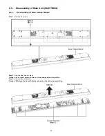
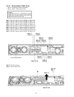
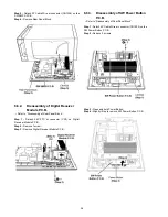
Step 5 :
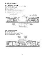
Detach 2P Cable Wire at connector (CN1006) on the
SW SMPS P.C.B..
Step 6 :
Remove Rear Panel Block.
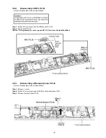
8.6.2.
Disassembly of Digital Receiver
Module P.C.B.
• Refer to “Disassembly of Rear Panel Block”.
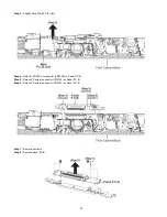
Step 1 :
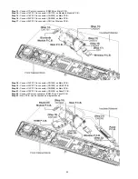
Detach 24P FFC at connector (CN1) on Digital
Receiver Module P.C.B..
Step 2 :
Remove 1 screw.
Step 3 :
Remove Digital Receiver Module P.C.B..
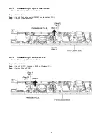
8.6.3.
Disassembly of SW Power Button
P.C.B.
• Refer to “Disassembly of Rear Panel Block”.
Step 1 :
Detach 4P Cable Wire at connector (CN1002) on the
SW Power Button P.C.B..
Step 2 :
Remove 2 screws.
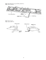
Step 3 :
Press and hold Power Button.
Step 4 :
Slightly lift up to remove SW Power Button P.C.B..
Содержание SU-HTB880EB
Страница 4: ...4 1 2 Caution for AC Cord For EB only ...
Страница 19: ...19 7 Troubleshooting Guide This section is not available at the time of issue ...
Страница 22: ...22 8 3 Type of Screws 8 3 1 Main Unit SU HTB880 8 3 2 Active Subwoofer SB HWA880 ...
Страница 23: ...23 8 4 Main Parts Location Diagram 8 4 1 Main Unit SU HTB880 8 4 2 Active Subwoofer SB HWA880 ...
Страница 46: ...46 ...
Страница 56: ...56 ...
Страница 58: ...58 ...
Страница 98: ...98 ...
Страница 104: ...104 ...

