background image

12 Printed Circuit Board and Wiring Connection Diagram

1

2

3

4

5

6

7

8

9

10

11

12

13

A

B

C

D

E

F

G

H

D90

(CHG)

R90

E

C

B

Q2

Q12

ICP11

S801

S802

S804

S803

S805

S806

1

5

10

15

20

25

26

30

35

40

45

50

IC503

1

2

CN101

3

4

5

6

8

9

10

11

12

13

14

15

16

19

20

18

17

21

22

23

24

7

S201

Q704

C B E

C

B

E

E

C

B

Q903

E

C

B

Q901

C

C

Q11

B

B

E

E

C16

C9

C1

1

C40

R809

R807

R806

R81

1

R2

R808

R810

C12

L13

L14

L11

C13

L12

C531

C520

C518

C510

C534

C523

C522

C536

C521

C535

C524

C527

C537

C51

1

C519

C529

R519

R527

R204

R525

R524

R508

R506

R518

C711

C702

C539

C703

C704

C528

C901

R904

RJ903

R536

R526

D901

S310

OFF

ON

L504

L502

L704

C101

C904

C903

R910

R901

E

C

B

Q902

E

C

B

Q905

R702
R701

C305

R328

R319

R332

R322

R324

R956

R323

R327

C506

C20

C22

C17

C37

C21

C18

C10

R22

R29

R28

R16

R10

R517

R31

R21

R13

1

5

10

15

20

25

30

32

33

35

40

45

50

55

60

64

65

70

75

80

85

90

95

96

100

105

110

115

120

125

128

97

IC501

1

5

10

12

13

15

20

24

25

30

35

36

40

37

45

48

IC11

1

5

10

15

20

21

25

30

35

40

41

45

50

55

60

61

65

70

75

80

IC301

1

4

5

8

IC302

E

C

B

Q13

E

C

B

Q14

E

C

B

Q15

S

D

G

Q502

C

B

E

Q201

E

C

B

Q19

E

C

B

Q301

E

C

B

Q16

R306

R17

D1

1

C38

C19

C42

R14

R15

C561

C570

C505

C517

C538

C504

C513

R523

R507

R502

R505

R504

R516

R534

R528

R531

R521

R520

R515

R513

R512

R509

R51

1

R514

X501

C712

C41

C15

C707

C708

C47

R705

R706

R704

R703

R707

R708

L901

L903

L902

C302

C321

R329

R330

R307

R361

R335

R325

R321

R313

R532

R529

C301

R304

R317

C14

C27

C28

C701

C507

C705

C201

C706

JK12

EXT BATT

S

JK11

JK701

G

G

R

L

S

K

HEADPHONE

C

CN12

VOL(+)

VOL(-)

HOLD

SHORT

LAND

SL101

GND

RF

V

DD

VREF

1 2 3

SL-CT520(EG,EB,EE,SG) P.C.B.

(SIDE: A)

(SIDE: B)

Note: This printed circuit board diagram may be modified at any time with the development of new technology.

2 R03/LR03(UM-4)
BATTERIES      3V

R1

OPTICAL PICK-UP

E

C

B

Q31

R33

D31

ICP12

DC IN      4.5V

(REP3872C-M)

SL-CT520EB / SL-CT520EG / SL-CT520EE / SL-CT520SG

19

Содержание SL-CT520EB

Страница 1: ...ow Type SL CT520GK only Please use this manual together with the service manual for Model No SL CT520EB EG EE SG Order No AD0502004C0 2005 Matsushita Electric Industrial Co Ltd All rights reserved Unauthorized copying and distribution is a violation of law 1 PDF created with pdfFactory Pro trial version www pdffactory com ...

Страница 2: ...l characteristics important for safety Furthermore special parts which have purposes of fire retardant resistors high quality sound capacitors low noise resistors etc are used When replacing any of components be sure to use only manufacture s specified parts shown in the parts list The parenthesized indications in Remarks columns specify the areas and colours A Blue Type P Pink Type S Silver Type ...

Страница 3: ... 1 P P2 RPK2325 RPK2289 GIFT BOX 1 Y P3 RPQ1849 RPQ1848 PAD 1 Ref No Change of Parts No Part Name Description Pcs Remarks SL CT520SG S SL CT520GT CABINET PARTS 13 RGN2805 H RGN2813 H NAME PLATE 1 ACCESSORIES A2 L0BAB0000190 L0BAB0000183 STEREO EARPHONES 1 A3 N2QCBD000048 N2QCBD000049 WIRED REMOTE CONROL 1 A5 RFEA444Z S RFEA439G U AC ADAPTOR 1 A6 RQT7816 B RQT7820 K OPERATING INSTRUCTIONS 1 CHINESE...

Страница 4: ...All rights reserved Unauthorized copying and distribution is a violation of law SL CT520EB SL CT520EG SL CT520EE SL CT520SG Colours A Blue Type P Pink Type SL CT520SG only S Silver Type Y Yellow Type SL CT520SG only Portable CD Player AD0502004C0 ...

Страница 5: ...ions described below on the traverse deck after replacing 12 8 Automatic Adjustment Results Display Function Self Check Function 13 8 1 How to display automatic adjustment results 13 8 2 Display of automatic adjustment results Self Check Function 13 9 Type Illustration of ICs Transistors and Diodes 14 10 Schematic Diagram Notes 14 11 Schematic Diagram 15 12 Printed Circuit Board and Wiring Connect...

Страница 6: ...c External battery case RFA2666 H 1 pc Rechargeable batteries with case for SL CT520EE only RFKHHR4AGE 2 pcs Rechargeable batteries with case for SL CT520SG only RFKHHR4AGTB 2 pcs Power plug adaptor for SL CT520SG only K2DA42E00001 1 pc 1 Accessories 2 Location of Controls Battery compartment Lens Headphone jack A Open Play Pause Stop Turn off Battery case terminal DC IN jack Charge lamp C A B Pla...

Страница 7: ...3 Precaution of Laser Diode 4 SL CT520EB SL CT520EG SL CT520EE SL CT520SG ...

Страница 8: ...2 Caution when replacing traverse deck The new traverse deck short circuits by the short pin the foil B and short lands to protect the laser diode against electrostatic breakdown Be sure to replace to new one following procedures 1 Remove the short pin from the FFC and then connect it to the connector 2 Cut the foil B Refer to Fig 4 1 Take care not to make contact with cutting point each other 3 U...

Страница 9: ...embly after operation checks or replacement reverse the respective procedures Special reassembly procedures are described only when required 5 1 Checking for the P C B 5 1 1 Checking for the P C B A side Check the P C B A side as shown below 5 Operation Checks and Component Replacement Procedures 6 SL CT520EB SL CT520EG SL CT520EE SL CT520SG ...

Страница 10: ...low the Step 1 Step 5 of item 5 1 1 Check the P C B B side as shown below 5 2 Replacement for the CD lid unit open spring 1 open spring 2 and retainer plate Follow the Step 1 Step 4 of item 5 1 1 7 SL CT520EB SL CT520EG SL CT520EE SL CT520SG ...

Страница 11: ...5 3 Replacement for the traverse motor Follow the Step 1 Step 4 of item 5 1 1 8 SL CT520EB SL CT520EG SL CT520EE SL CT520SG ...

Страница 12: ...5 4 Replacement for the optical pick up Follow the Step 1 Step 4 of item 5 1 1 Follow the Step 1 Step 2 of item 5 3 9 SL CT520EB SL CT520EG SL CT520EE SL CT520SG ...

Страница 13: ...5 5 Replacement for the rest switch Follow the Step 1 Step 4 of item 5 1 1 Follow the Step 1 Step 2 of item 5 4 10 SL CT520EB SL CT520EG SL CT520EE SL CT520SG ...

Страница 14: ...y Remote control display Press PLAY and STOP button After 15 seconds it is displayed for 2 seconds In case of this display it may be causing for abnormally movements of traverse deck touching failure of REST detect switch and coming off or cutting off the flexible P C B It is necessary for confirmation or repair and replacement each parts 11 SL CT520EB SL CT520EG SL CT520EE SL CT520SG ...

Страница 15: ...earch operation at either low or high speed in both the forward and reverse directions replacing it Replace the traverse deck only after the problem is identified 7 1 3 Checking playability 1 Play the 0 7 mm black dot and the 0 7 mm wedge on the playability test disc SZZP1054C and verify that no sound skip or noise occurs 2 Play the middle tracks of the uneven test disc SZZP1056C and verify that n...

Страница 16: ...al state by exchanging the traverse deck circuit is incorrect The followings are the contents of the automatic adjustment result displays Self Check Function 3 Press the STOP TURN OFF button once 4 An automatic adjustment result is displayed on the remote control display Follow the below steps when E F is displayed Cause All adjustments TGC FGC TBC FBC are set beyond the limit Check if 1 the optic...

Страница 17: ...d herein shall be regarded as reference information when probing defect point because it may differ from an actual measuring value due to difference of Measuring instrument and its measuring condition and product itself Measurement conditions AC adaptor is used for power supply Set the hold switch to ON The parenthesized is the voltage for test disc 1 kHz L R 0 dB in play mode and the other for no...

Страница 18: ...OIL TRACKING COIL 1 2 24 3 4 5 6 7 8 9 10 11 12 13 14 15 CN101 16 17 18 19 20 21 22 23 1 2 24 3 4 5 6 7 8 9 10 11 12 13 14 15 16 17 18 19 20 21 22 23 STAND BY VC RF VB VA GCTL VF VE Vcc VREF MPD LD GND TR TR FO FO TRV TRV SP SP GND REST TRAVERSE MOTOR S202 REST SWITCH SPINDLE MOTOR M M Q201 2SB709ATX LASER POWER DRIVE R531 2 2 S201 LASER ON OFF SL101 SHORT LAND A B C D E F G H I C D E F G H I J 1 ...

Страница 19: ...06 39K R519 47K C510 0 039 C519 560P K L M N O P Q A B R527 2 2K C536 1 R526 2 2K R516 100K C518 560P VREF RF R523 10 C517 1 1 V DD V SS 2 DQ0 3 DQ1 4 V SS Q 5 DQ2 6 DQ3 7 V DD Q 8 DQ4 9 DQ5 10 V SS Q 11 DQ6 12 DQ7 13 V DD Q 14 LDQM 15 WE 16 CAS 17 RAS 18 CS 19 BA 20 A10 AP 21 A0 22 A1 23 A2 24 A3 25 V DD DQ15 DQ14 V SS Q DQ13 DQ12 V DD Q DQ11 DQ10 V SS Q DQ9 DQ8 V DD Q NC RFU UDQM CLK CKE NC A9 A...

Страница 20: ...R15 56K L903 L902 R707 1K R708 1K R901 2 2K R910 2 2K Q903 UN5113TX BUZZER CONT C705 4V220 C706 4V220 R705 2 2 Q704 B1GFGCAA0001 MUTING R706 2 2 R702 560 R701 560 R703 5 6 R704 5 6 Q901 UN5114TX MUTING CONT Q902 UNR521000L MUTING CONT Q905 UN5215TX MUTING CONT C904 0 1 Y Z B A SL CT520 EG EB EE SG CIRCUIT DIAGRAM JK701 HEADPHONE L R G S G K RJ903 10 R904 1K R956 33 C901 150P C903 1000P JK12 EXT BA...

Страница 21: ...SL CT520EB SL CT520EG SL CT520EE SL CT520SG 18 ...

Страница 22: ... 55 60 64 65 70 75 80 85 90 95 96 100 105 110 115 120 125 128 97 IC501 1 5 10 12 13 15 20 24 25 30 35 36 40 37 45 48 IC11 1 5 10 15 20 21 25 30 35 40 41 45 50 55 60 61 65 70 75 80 IC301 1 4 5 8 IC302 E C B Q13 E C B Q14 E C B Q15 S D G Q502 C B E Q201 E C B Q19 E C B Q301 E C B Q16 R306 R17 D11 C38 C19 C42 R14 R15 C561 C570 C505 C517 C538 C504 C513 R523 R507 R502 R505 R504 R516 R534 R528 R531 R521...

Страница 23: ...SL CT520EB SL CT520EG SL CT520EE SL CT520SG 20 ...

Страница 24: ... AUDIO OUTPUT BUFFER 77 REGULATOR 14 REGON FLAG0 103 70 AV DD 2 64 AV SS 2 SERVO CPU 74 LOOUTR HPV DD L HPCNT 76 HPV SS R HPV DD R HPOUTL HPV SS L 82 80 78 79 AVDD1 AVSS1 HPOUTR 75 72 81 HPOUTL 98 STAT AD PVcc 33 HPCNT CIRC RAM SUBCODE INTERFACE BUS CONTROL UNIT 96 65 MDATA ARFIN 95 MCLK 67 IREF SERIAL OUTPUT INTERFACE DAC BLKCK 99 NCAS 7 NRAS 8 FS CONVERTER NRAS 6 NWE 9 CKE NWE 125 SDRCK CLK 19 B...

Страница 25: ...CHARGE1 EXT BATT S805 VOL S806 VOL C2BBGF000595 IC301 SYSTEM CONTROL 15 HPCNT ECS ECS 67 DC IN DET Q15 69 RIO LED DRIVE B6 Q2 D90 CHG SEG12 LED 40 HPCNT B9 C3ABMG000207 IC503 DRAM A0 10 16 DQ0 15 20 24 27 32 CAS 34 CKE WE 17 15 RAS 2 3 5 6 8 9 11 12 39 40 42 43 45 46 48 49 35 CLK 19 BA 36 UDQM 14 LDQM B4 7 13 38 44 VDDQ VSS 26 50 B4 1 25 VDD CS SK DO DI GND 5 VCC 8 1 2 3 4 ECS MCLK MDATA C3EBCG000...

Страница 26: ...gnal output 71 AVSS GND 72 VREF I Reference voltage input 73 6KEY Not used open 74 DOCTOR I Doctor mode AD input 75 VMONI TOR2 I PVCC1 voltage measurement input 76 VMONI TOR I Battery voltage GND measurement input 77 VMONI TOR3 I Connected to GND via resistor 78 KEY2 I Operation key signal input 79 KEY1 I Operation key signal input 80 OPEN I CD lid open switch input 14 2 IC501 MN6627962JB Servo Am...

Страница 27: ...ut 84 DVSS2 GND 85 X1 I Crystal oscillator connected terminal F 16 9 MHz 86 X2 O 87 IOVDD2 I Power supply terminal 88 DVDD2 I Power supply terminal 89 VM4SEL OFF Connected to DVDD2 via resistor 90 PMSEL1 FBAL Connected to DVDD2 via resistor 91 PMSEL2 TBAL Connected to GND via resistor 92 LASER SEL BDO Connected to GND via resistor 93 CLVS RFDET Not used open 94 IPFLAG2 VDET Not used open 95 MCLK I...

Страница 28: ...use it Be sure to carry Rechargeable Battery in this Carrying Case If not may either heat or ignite by shorting with a metal Battery without Carrying Case Replacement parts will be supplied for Carrying Case RXQ0449 without Rechargeable Battery To your customers delivery Rechargeable Battery together with Carrying Case to prevent shorting accidents that may occur when Rechargeable Battery is carri...

Страница 29: ...ER 1 9 RKM0521 W MIDDLE CABINET 1 10 RMR1670 K LOCK PLATE 1 11 RMR1671 W LENS 1 12 RGV0340 S KNOB HOLD 1 13 RGN2806 H NAME PLATE 1 EGS EGA EBS EBA Ref No Part No Part Name Description Pcs Remarks 13 RGN2826 H NAME PLATE 1 EES EEA 13 RGN2805 H NAME PLATE 1 SGS SGA SGP SGY 14 RQLS0244 1 CAUTION LABEL 1 15 RMC0611 DETECT SPRING 1 16 XQN14 BG3FC SCREW 1 A1 RFKHHR4AGE RECHARGEABLE BATT ASS Y 2 EES EEA ...

Страница 30: ...BCG000096 IC 1 IC501 MN6627962JB IC 1 IC503 C3ABMG000207 IC 1 ICP11 ERBSE1R00U IC PROTECTOR 1 ICP12 ERBSE1R00U IC PROTECTOR 1 Ref No Part No Part Name Description Pcs Remarks JK11 RJJ43K09 C JK DC IN 1 K2EB2B000006 JK12 K2FB2B000002 JK EXT BATT 1 JK701 K2HC106B0019 JK HEADPHONES 1 L11 G1C331K00008 COIL 1 L12 G1A101D00009 COIL 1 L13 G1C101K00033 COIL 1 L14 G1C101K00033 COIL 1 L502 G1C101K00033 COIL...

Страница 31: ...GB103JA002 R526 ERJ3GEYJ222 1 10W 2 2K 1 R527 ERJ3GEYJ222 1 10W 2 2K 1 R528 ERJ3GEYJ104 1 10W 100K 1 R529 ERJ3GEY0R00 1 10W 0 1 R531 ERJ3GEYJ2R2 1 10W 2 2 1 R532 ERJ3GEYJ220 1 10W 22 1 R534 ERJ3GEYJ223 1 10W 22K 1 R536 ERJ3GEY0R00 1 10W 0 1 R701 ERJ3GEYJ561 1 10W 560 1 R702 ERJ3GEYJ561 1 10W 560 1 R703 ERJ3GEYJ5R6 1 10W 5 6 1 R704 ERJ3GEYJ5R6 1 10W 5 6 1 R705 ERJ3GEYJ2R2 1 10W 2 2 1 R706 ERJ3GEYJ2...

Страница 32: ...18 Cabinet Parts Location 29 SL CT520EB SL CT520EG SL CT520EE SL CT520SG ...

Страница 33: ...19 Traverse Unit Parts Location 30 SL CT520EB SL CT520EG SL CT520EE SL CT520SG ...

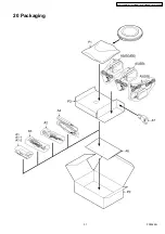
Страница 34: ...20 Packaging 31 SL CT520EB SL CT520EG SL CT520EE SL CT520SG F0502KH ...

Отзывы: