Wiring
© Panasonic Industrial Devices SUNX Co., Ltd. 2020
52
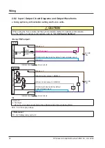
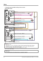
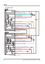
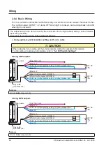
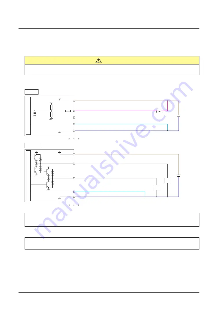
2-5-2 Input / Output Circuit Diagrams and Output Waveforms
●
Using optical synchronization setting and 5-core cable
CAUTION
When using the 5-core cable, set the synchronization method to optical synchronization.
For the setting of optical synchronization, refer to
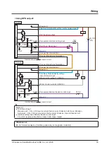
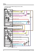
<Using PNP output>
Main circuit
Main circuit
0.1μF
470Ω
Emitter
Receiver
Internal circuit
Internal circuit
Users’ circuit
Users’ circuit
(Brown) +V
(Brown) +V
(Pink) Test input
(Pale blue) Output polarity setting / Lockout release input
(Pale blue) Output polarity setting /
Lockout release input
(Blue) 0V
(Blue) 0V
(Black) Control output 1 (OSSD 1)
(White) Control output 2 (OSSD 2)
*S1
K1
K2
+ 24V DC
+20
-30
%
−
+ 24V DC
+20
-30
%
−
6.8kΩ
6.8kΩ
*S1
Switch S1
●
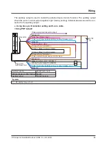
Test input
Vs to Vs − 2.5V (sink current 5mA or less): Emission halt, Open: Emission (Note)
Note: Vs is the supply voltage.
<Reference>
K1, K2: Safety relay unit, etc.
Содержание SF4D-*-01 Series
Страница 2: ... Panasonic Industrial Devices SUNX Co Ltd 2020 2 MEMO ...
Страница 6: ... Panasonic Industrial Devices SUNX Co Ltd 2020 6 MEMO ...
Страница 120: ...Functions Panasonic Industrial Devices SUNX Co Ltd 2020 120 MEMO ...
Страница 134: ...Troubleshooting Panasonic Industrial Devices SUNX Co Ltd 2020 134 MEMO ...
Страница 168: ... Panasonic Industrial Devices SUNX Co Ltd 2020 168 MEMO ...


