


23
9.3.
Disassembly Procedure
No.
Item
Fig
Removal
1
Tripod piece,
Access panel light
Fig.D1
5 Screws (A)
Tripod piece
Fig.D2
GND O ring
Access panel light
2
Front case
Fig.D3
Front case
3
Rear cover
Fig.D4
1 Screw (B)
1 Screw (C)
Rear cover
4
R cover
Fig.D5
2 Screws (D)
4 Locking tabs
Fig.D6
R cover
5
Top cover
Fig.D7
4 Locking tabs
Top cover
6
Lens piece,
Lens protection glass,
Lens damper
Fig.D8
3 Screws (E)
Lens piece
Lens protection glass
Lens damper
7
Side case L unit
Fig.D9
8 Screws (F)
2 Screws (G)
FP4802(Flex)
Case O ring
Side case L unit
Fig.D10
Notes on installation of the
Case O ring
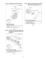
8
Lens unit / Main P.C.B. Fig.D11
4 Screws (H)
FP6961(Flex)
P6901(Connector)
FP6903(Flex)
Lens unit / Main P.C.B.
9
Radiation plate
Fig.D12
4 Screws (I)
Radiation plate
10
Battery catcher unit
Fig.D13
2 Screws (J)
FP6905(Flex)
Battery catcher unit
11
Main P.C.B.,
Jack P.C.B.
Fig.D14
1 Screw (K)
FP6931(Flex)
FP6971(Flex)
2 Locking tabs
FP6001(Connector)
Main P.C.B.
Jack P.C.B.
12
Lens unit
Fig.D15
FP6931(Flex)
FP6971(Flex)
1 Screw (L)
1 Locking tab
Lens unit
13
Battery case
Fig.D16
1 Screw (M)
2 Locking tabs
Battery case
14
Front P.C.B.
Fig.D17
1 Screw (N)
2 Ribs
FP4801(Flex)
Front P.C.B.
15
LCD unit
Fig.D18
R base rubber
1 Screw (O)
Fig.D19
3 Screws (P)
GND O ring
LCD unit
16
LCD hinge unit,
Monitor P.C.B.
Fig.D20
4 Screws (Q)
Packing angle
4 Screw O rings
2 Screws (R)
Fig.D21
2 Locking tabs
LCD case top
FP8101(Flex)
3 Locking tabs
FP8102(Flex)
LCD hinge unit
Monitor P.C.B.
17
LCD panel
Fig.D22
Reflection sheet
Lighting plate
Diffusion sheet
Prism sheet B
Prism sheet A
Light guide holder
LCD panel
LCD shield case
LCD case bottom unit
Fig.D23
Notes on installation of the
LCD O ring
18
Speaker unit,
Operation FPC unit
Fig.D24
9 Screws (S)
Operation angle
Earth angle
Speaker unit
Fig.D25
1 Screw (T)
Screw O ring
SS operation angle
Zoom operation angle
SS button rubber unit
Zoom OP rubber unit
Operation FPC unit
Fig.D26
NOTE: (When Installing)
19
CCD unit,
Optical filter
Fig.D27
2 Screws (P)
CCD cushion rubber
CCD unit
Optical filter
20
IRIS unit
Fig.D28
Solder (8 points)
3 Screws (Q)
1 Rib
Fig.D29
IRIS unit
21
Zoom motor unit
Fig.D30
2 Screws (R)
Zoom motor unit
22
Focus motor unit
Fig.D31
2 Screws (S)
Focus motor unit
23
Master flange,
4th moving frame unit,
3rd moving frame unit
Fig.D32
3 Screws (T)
Master flange
4th moving frame unit
3rd moving frame unit
24
Guide pole S,
Guide pole,
2nd moving frame unit
Fig.D33
Guide pole S
Guide pole
2nd moving frame unit
No.
Item
Fig
Removal
Содержание SDR-SW21EB
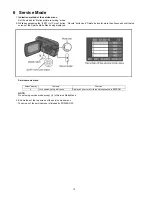
Страница 9: ...9 4 Specifications For NTSC areas For PAL areas ...
Страница 10: ...10 ...
Страница 14: ...14 7 Troubleshooting Guide 7 1 Confirmation Flow of Waterproof ...
Страница 15: ...15 7 2 Airtight Inspection with Air Leak Tester ...
Страница 16: ...16 7 3 Air Leak Tester RFKZ0528 Operating Instruction ...
Страница 17: ...17 ...
Страница 18: ...18 ...
Страница 19: ...19 ...
Страница 22: ...22 9 Disassembly and Assembly Instructions 9 1 Disassembly Flow Chart 9 2 PCB Location ...
Страница 27: ...27 Fig D10 9 3 8 Removal of the Lens unit Main P C B Fig D11 ...
Страница 30: ...30 Fig D19 9 3 16 Removal of the LCD hinge unit and Monitor P C B Fig D20 ...
Страница 31: ...31 Fig D21 9 3 17 Removal of the LCD panel Fig D22 ...
Страница 32: ...32 Fig D23 9 3 18 Removal of the Speaker unit and Operation FPC unit Fig D24 ...
Страница 33: ...33 Fig D25 Fig D26 ...
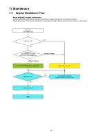
Страница 38: ...38 11 Maintenace 11 1 Regular Maintenance Flow ...
Страница 39: ...39 11 2 Component Kits of Waterproof ...
Страница 56: ...S 16 ...
Страница 65: ...23 B10 B9 9 74 21 20 19 16 17 18 15 14 13 12 3 7 5 B8 B7 B6 B5 4 8 6 11 22 10 S7 2 LCD Section S 25 ...
Страница 69: ...S7 6 Waterproof Kit LCD Unit S 29 402 402 402 402 402 402 402 402 402 402 402 402 402 402 ...


