
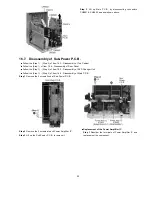


1. Turn off by pressing power SW in the body.
2. Unplug AC power cord after the indication of [GOOD-BYE],
then disassemble the body.
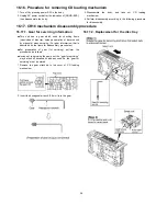
16.17.1. Gear for servicing information
•
•
•
•
This unit has a gear which used for checking items
(open/close of disc tray, up/down operation of traverse unit
by manually) when servicing. (For gear information, that is
described on the items for disassembly procedures.)
•
•
•
•
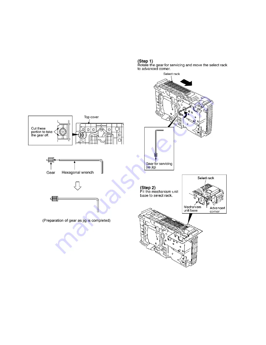
For preparation of gear (for servicing), perform
the
procedures as follows.
•
•
•
•
In case of re-servicing the same set, the “gear for servicing”
may be took off because it had been used. So, the “gear for
servicing” must be stored.
1. Remove the gear attached to top cover of CD loading
mechanism.
2. Insert the hexagonal wrench (2.5mm) into the gear.
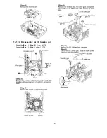
3. Disassemble
the
body,
and
take
out
CD
loading
mechanism.
4. Perform disassembly according to the following procedure
for disassembly.
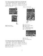
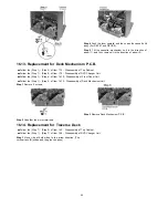
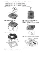
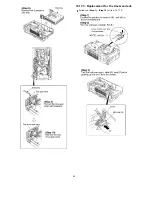
16.17.2. Replacement for the disc tray
16.16. Procedure for removing CD loading mechanism
16.17. CR16 mechanism disassembly procedure
38
Содержание SC-TM900DVD
Страница 9: ...10 Operation Procedures 9 ...
Страница 10: ...10 ...
Страница 11: ...11 Disc information 11 ...
Страница 12: ...12 ...
Страница 15: ...15 ...
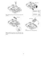
Страница 35: ...Step 2 Remove DVD traverse deck by rotating to the arrow direction 35 ...
Страница 39: ...39 ...
Страница 40: ...16 17 3 Replacement for the traverse deck Follow the Step 1 Step 10 of item 16 17 2 40 ...
Страница 42: ...42 ...
Страница 43: ...43 ...
Страница 45: ...45 ...
Страница 46: ...46 ...
Страница 47: ...47 ...
Страница 48: ...48 ...
Страница 49: ...49 ...
Страница 50: ...50 ...
Страница 51: ...51 ...
Страница 52: ...52 ...
Страница 53: ...53 ...
Страница 54: ...54 ...
Страница 55: ...55 ...
Страница 65: ...18 3 1 Cassette Deck Section 18 3 2 Adjustment Point 18 3 Alignment Points 65 ...
Страница 77: ...20 Voltage Measurement This section is not available at time of issue 77 ...
Страница 102: ...6CC 6CC 54 4 4 54 6CC 2 2 6 6CC 2 54 54 4 6 7 7 7 7 0 0 0 0 23 0 2 2 2 2 1 1 1 2 2 2 2 2 2 2 2 2 2 2 2 2 2 6 4 54 4 2 ...
Страница 103: ... 54 2 352 4 352 2 35 7 2 54 7 54 6CC 2 54 2 7 7 7 7 9 9 2 3 6 4 2 2 2 2 2 2 7 7 2 2 2 2 2 2 2 2 2 2 2 2 7 7 2 ...
Страница 107: ...35 6 6 7 7 7 7 7 7 6 U 2 2 2 0 2 1 2 2 1 2 2 1 2 1 2 2 2 4 6 35 ...
Страница 109: ...0 7 7 7 2 2 2 3 4 6 EW ODEL GT IC OTE ATERIAL 3IZE MODIFIED 0 4 25 ...
Страница 110: ...2 0 7 2 0 5NIT MM 0ARTS NO AME PPROVED HECKED 3 ...
Страница 111: ......
Страница 112: ......
Страница 113: ......
Страница 114: ......
Страница 115: ......
Страница 116: ...116 ...
Страница 117: ...117 ...
Страница 135: ...B0ACCK000005 MA2J72800L Cathode Anode Ca A B0AACK000004 MA2C16500E B0JAPG000019 A Ca Cathode Anode 135 ...
Страница 139: ...26 1 Deck Mechanism RAA3413 S 26 1 1 Deck Mechanism Parts Location 139 ...
Страница 140: ...140 ...
Страница 142: ...26 2 DVD Loading Mechanism 26 2 1 DVD Loading Mechanism Parts Location 142 ...
Страница 143: ...143 ...
Страница 145: ...26 3 Cabinet 26 3 1 Cabinet Parts Location 145 ...
Страница 146: ...146 ...
Страница 147: ...147 ...
Страница 188: ...3 Connection of the Wiring Diagram 4 Cabinet Parts Location 5 service m speaker 11 ...
Страница 192: ...3 Connection of the Wiring Diagram 9 service m speaker ...
Страница 193: ...4 Cabinet Parts Location 3 10 service m speaker ...
Страница 196: ...Step 1 Detach the black and blue wires from Woofer Step 2 Remove 4 screws from Woofer 13 service m speaker ...
Страница 198: ...3 Connection of the Wiring Diagram 4 Cabinet Parts Location 15 service m speaker ...
Страница 203: ...3 Connection of the Wiring Diagram 4 Cabinet Parts Location 20 service m speaker ...


