background image

Step 4: Remove the Woofer by detaching the (+) white and (-) blue wires.

1.4. Assembly of Subwoofer Unit

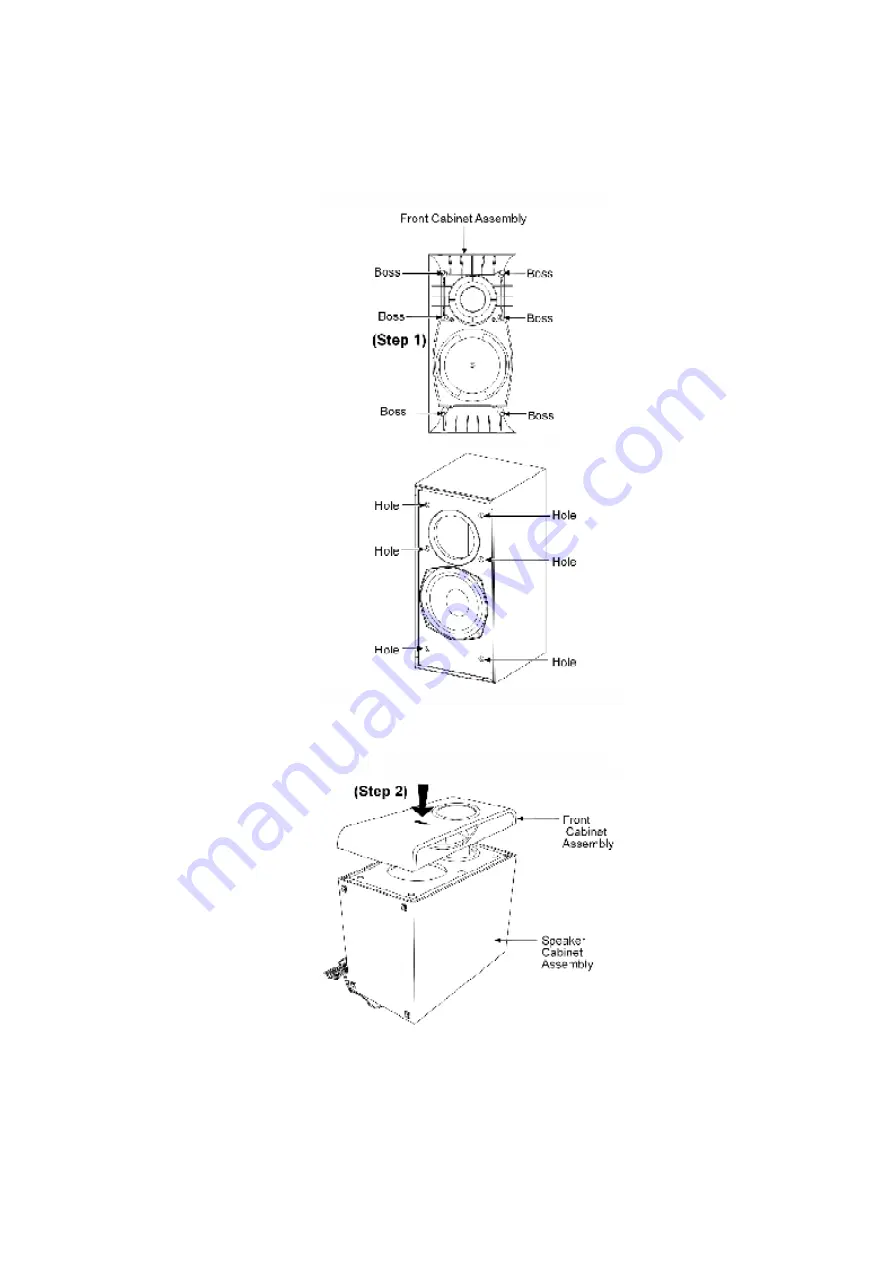
Step 1: Scrape off using the scriber and clean up the remaining glue at the 6 bosses and 6 holes 
as arrow shown and replace with the normal glue.

Step 2: Fix the Front Cabinet Assembly firmly back to the Speaker Cabinet Assembly.

2. Connection of the Speaker Cables

- Be sure to connect speaker cables before connecting the AC 

Содержание SB-W740

Страница 1: ...ORDER NO MD0512499C7 A6 Subwoofer System SB W740P Colour S Silver Type SPECIFICATIONS ...

Страница 2: ...on is measured by the digital spectrum analyzer System SC HT740GCPS Music Center SA HT740GCPS Front Speaker SB FS740P S Surround Speaker SB FS741P S Center Speaker SB PC740P S Subwoofer SB W740P S System SC HT740P S Music Center SA HT740P S Front Speaker SB FS740P S Surround Speaker SB FS741P S Center Speaker SB PC740P S Subwoofer SB W740P S System SC HT740PC S Music Center SA HT740PC S Front Spea...

Страница 3: ...This section describes procedures for checking the operation of the major printed circuit boards and replacing the main components 2 For reassembly after operation checks or replacement reverse the respective procedures Special reassembly procedures are described only when required 3 Select items from the following index when checks or replacement are required 4 Refer to the Parts No on the page o...

Страница 4: ...sembly of Speaker Cabinet Assembly 1 1 Disassembly flow chart The following chart is the procedure for disassembling the casing and inside parts for internal inspection when carrying out the servicing To assemble the unit reverse the steps shown in the chart as below 1 2 Disassembly of Front Cabinet Assembly ...

Страница 5: ...f the Speaker unit Push the steel rule forward and backward as arrow shown Step 3 Insert a flathead screwdriver into the grooves as arrow shown Ensure that the screwdriver is above the Steel rule Step 4 Use the screwdriver to slightly push up the Front Cabinet Assembly as arrow shown ...

Страница 6: ...the boss area push up as arrow shown to open the boss Caution Do not exert strong force as it may damage the Front Cabinet Assembly 1 3 Disassembly of Woofer Follow step 1 to step 5 of item 1 2 Step 1 Remove all 4 screws from the Woofer ...

Страница 7: ...Step 2 Insert a steel rule between the Woofer and Speaker Cabinet Assembly to push out the Woofer Step 3 Take out the Woofer unit ...

Страница 8: ...e off using the scriber and clean up the remaining glue at the 6 bosses and 6 holes as arrow shown and replace with the normal glue Step 2 Fix the Front Cabinet Assembly firmly back to the Speaker Cabinet Assembly 2 Connection of the Speaker Cables Be sure to connect speaker cables before connecting the AC ...

Страница 9: ...rt circuit positive and negative speaker wires Be sure to connect only positive white wires to positive terminals and negative blue wires to negative terminals Incorrect connection can damage the speakers Positioning the speakers How you set up your speakers can affect the bass and the sound field Note the following points Place the speakers on flat secure bases Placing speakers too close to floor...

Страница 10: ...face Main unit Note Keep your speakers at least 10 mm 13 32 away from the system for proper ventilation To allow for proper ventilation and to maintain good airflow around the main unit position it with at least 5 cm 2 of space on all sides Do not block the ventilation holes of the main unit Center speaker Vibration caused by the center speaker can disrupt the picture if it is placed directly on t...

Страница 11: ...e speakers e g Surround speaker Notes on speaker use You can damage your speakers and shorten their useful life if you play sound at high levels over extended periods Reduce the volume in the following cases to avoid damage When playing distorted sound When the speakers are reverberating due to a record player noise from FM broadcasts or continuous signals from an oscillator test disc or electroni...

Страница 12: ...3 Connection of Wiring Diagram 4 Exploded view 4 1 Cabinet Parts Location ...

Страница 13: ...4 2 Packaging Note The diagram below shows the packaging for SB W740P S ...

Страница 14: ......

Страница 15: ...Part No Part Name Description Remarks CABINET AND CHASSIS 1 RYQX0230 SPEAKER CAB ASS Y M 1 1 RMFX0046 HIMELON LONG M 1 2 RMFX0047 HIMELON SHORT M 2 RYBX0126 S FRONT CABINET ASS Y M 2 1 XTB3 10GFJ SCREW M 3 RKA0072 KJ LEG CUSHION M 4 RMQX0174 EVA PACKING WOOFER M 5 RMQX0166 EVA PACKING PORT M 6 RGNX0316 K SPEC LABEL M 7 XTB4 14AF K SCREW M PACKING MATERIALS P1 RPNX0356 POLYFOAM M P2 RPFX0157 MIRAMA...

Отзывы: