


45
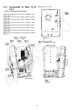
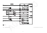
Step 12 Attach 5P Cable at the connector (CN2505) on Main
P.C.B. Ass'y.
Step 13 Attach 2P Wire at the connector (CN2104) on Main
P.C.B. Ass'y.
Step 14 Attach 2P Wire at the connector (CN2102) on Main
P.C.B. Ass'y.
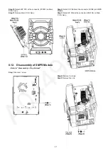
Step 15 Attach 13P Cable at the connector (CON2) on SMPS
Module.
Step 16 Attach 30P FFC at the connector (FP5001) on Main
P.C.B. Ass'y.
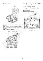
Step 17 Attach 5P FFC at the connector (FP8252) on Backend
P.C.B. Ass'y.
Step 18 Attach 6P FFC at the connector (FP8251) on Backend
P.C.B. Ass'y.
Step 19 Attach 24P FFC at the connector (FP8531) on Back-
end P.C.B. Ass'y.
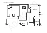
Step 20 Place the Main P.C.B. Ass'y, SMPS Module and Back-
end P.C.B. Ass'y on the insulated material.
Step 21 Check Backend P.C.B. Ass'y as diagram shown.
Содержание SA-VKX95EE
Страница 5: ...5 1 4 Caution For AC Cord For GS only Figure 1 3 ...
Страница 12: ...12 5 Location of Controls and Components 5 1 Remote Control Key Button Operation ...
Страница 13: ...13 5 2 Main Unit Key Button Operation ...
Страница 14: ...14 6 Service Mode 6 1 Service Mode Table ...
Страница 15: ...15 6 2 Sales Demonstration Lock Function ...
Страница 20: ...20 6 5 Self Diagnostic Mode 6 5 1 Self Diagnostic Mode Table 1 For DVD Module ...
Страница 21: ...21 6 5 2 Self Diagnostic Mode Table 2 For DVD Module ...
Страница 22: ...22 6 5 3 Self Diagnostic Mode Table 3 For DVD Module ...
Страница 25: ...25 6 6 Self Diagnostic Function Error Code 6 6 1 Mechanism Error Code Table 6 6 2 DVD Module Error Code Table ...
Страница 35: ...35 8 3 Main Components and P C B Locations ...
Страница 46: ...46 ...
Страница 58: ...58 ...
Страница 60: ...60 ...
Страница 86: ...86 ...
Страница 96: ...96 ...
Страница 100: ...100 ...


