2
3 Service Navigation---------------------------------------------- 10
3.1. Service Information -------------------------------------- 10
3.2. Notes -------------------------------------------------------- 10
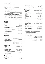
4 Specifications ---------------------------------------------------- 11
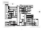
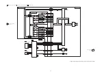
5 Block Diagram --------------------------------------------------- 13
5.1. System Control ------------------------------------------- 13
5.2. Audio -------------------------------------------------------- 17
5.3. Power Supply --------------------------------------------- 19
6 Schematic Diagram--------------------------------------------- 21
6.1. Schematic Diagram Notes ----------------------------- 21
6.2. Main (I/O Expansion) Circuit -------------------------- 23
6.3. Main (Fan LED) Circuit --------------------------------- 24
6.4. Main (DSP) Circuit --------------------------------------- 25
6.5. Main (Amp BTL) Circuit (1/2)-------------------------- 26
6.6. Main (Amp BTL) Circuit (1/2)-------------------------- 27
6.7. Main (MICON) Circuit (1/2) ---------------------------- 28
6.8. Main (MICON) Circuit (2/2) ---------------------------- 29
6.9. Main (Amp Single) Circuit (1/2) ----------------------- 30
6.10. Main (Amp Single) Circuit (2/2) ----------------------- 31
6.11. Main (FE) Circuit ----------------------------------------- 32
6.12. Main (Karaoke) Circuit ---------------------------------- 33
6.13. Main (Digital-Power) Circuit (1/2) -------------------- 34
6.14. Main (Digital-Power) Circuit (2/2) -------------------- 35
6.15. Main (USB) Circuit --------------------------------------- 36
6.16. Main (AUX Tuner) Circuit ------------------------------ 37
6.17. Illumination Left, Illumination Right, Button
Right & USB Circuit-------------------------------------- 38
6.18. FL Display Circuit ---------------------------------------- 39
6.19. Volume Jog & Multi Control Circuit ------------------ 40
6.20. Button Left Circuit ---------------------------------------- 41
6.21. Mic, Illumination Jog & CD Interface Circuit ------- 42
6.22. SMPS Circuit (1/2) --------------------------------------- 43
6.23. SMPS Circuit (2/2) --------------------------------------- 44
7 Printed Circuit Board ------------------------------------------ 45
7.1. Main P.C.B. (Side A)------------------------------------- 45
7.2. Main P.C.B. (Side B)------------------------------------- 46
7.3. Illumination Left, Illumination Right & FL
Display P.C.B. --------------------------------------------- 47
7.4. Button Left, Button Right, Mic & USB P.C.B. ------ 48
7.5. Volume Jog, Illumination Jog & Multi Control
P.C.B.-------------------------------------------------------- 49
7.6. SMPS P.C.B. ---------------------------------------------- 50
8 Voltage and Waveform Measurement -------------------- 51
8.1. Voltage Measurement----------------------------------- 51
8.2. Waveform Chart ------------------------------------------ 59
9 Exploded View and Replacement Parts List ----------- 61
9.1. Cabinet Parts Location 1 ------------------------------- 61
9.2. Cabinet Parts Location 2 ------------------------------- 62
9.3. Cabinet Parts Location 3 ------------------------------- 63
9.4. Packaging (SC-MAX370GSK) ------------------------ 64
9.5. Packaging (SC-MAX770GSK) ------------------------ 65
9.6. Mechanical Replacement Part List ------------------ 67
9.7. Electrical Replacement Part List --------------------- 69
Содержание SA-MAX370GS
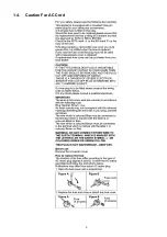
Страница 5: ...5 1 4 Caution For AC Cord ...
Страница 12: ...12 ...
Страница 22: ...22 ...
Страница 60: ...60 ...
Страница 66: ...66 ...


