Some chassis components may have sharp edges.
Be careful when disassembling and servicing.
11 Disassembly and Main Component Replacement
Procedures
“ATTENTION SERVICER”
1.
This section describes procedures for checking the operation of the major printed circuit boards and replacing the
main components.
2.
For assembly after operation checks or replacement, reverse the respective procedures.
Special reassembly procedures are described only when required.
3.
Select items from the following index when checks or replacement are required.
·
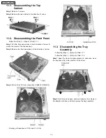
Disassembly the Top Cabinet
·
Disassembly the Front Panel
·
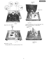
Disassembly the Tray Assembly
·
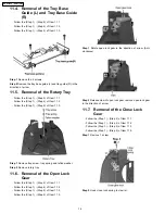
Removal of the Tray Base Guide (L) and Tray Base Guide (R)
·
Removal of the Rotary Tray
·
Removal of the Open Lock Gear
·
Removal of the Close Lock Gear
·
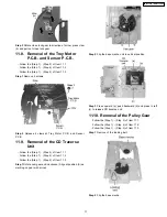
Removal of the Tray Motor P.C.B.and Sensor P.C.B.
·
Removal of the CD Traverse Unit
·
Removal of the Pulley Gear
·
Removal of the Loading Motor P.C.B.
·
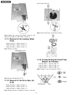
Removal of the Drive Gear (A) & (B)
·
Disassembly the Fixed Plate, Magnet and Clamper
·
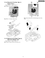
Removal of the Cam Gear & Support Piece
·
Removal of the Slide Plate (L) & (R) and Changer Lever
·
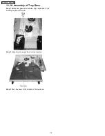
Assembly of Tray Base
13
SA-HT720P / SA-HT720PC
Содержание SA-HT720P
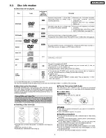
Страница 9: ...8 2 Disc information 9 SA HT720P SA HT720PC ...
Страница 25: ...25 SA HT720P SA HT720PC ...
Страница 44: ...SA HT720P SA HT720PC 44 ...
Страница 58: ...SA HT720P SA HT720PC 58 ...
Страница 63: ...63 SA HT720P SA HT720PC ...
Страница 64: ...64 SA HT720P SA HT720PC ...


