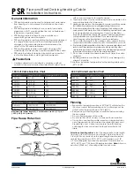
12.4.1.1. Adjustment procedure
1. While pressing STOP button on the main unit, press "5" on
the remote control unit.
2. Confirm that "J_xxx/yyy_zz" (display1/display2) is shown on
the front display.
For your information:
"yyy" and "zz" shown to the right have nothing to do with
the jitter value. "yyy" is the error counter, while "zz" is
the focus drive value.
Note:
Jitter value appears on the front display.
3. Play test disc T30 (center periphery).
4. Adjust tangential adjustment screw so that the jitter value is
minimized.
5. Play test disc T30 (center periphery).
6. Adjust tilt adjustment screw 1 so that the jitter value is
minimized.
7. Play test disc T30 (center periphery).
8. Adjust tilt adjustment screw 2 so that the jitter value is
minimized.
9. Repeat adjusting tilt adjustment screws 1 and 2 alternately
until the jitter value is minimized.
12.4.1.2. Important points
1. Make tangential adjustment first, and then make tilt
adjustment.
2. Repeat adjusting two or three times to find the optimum
point.
3. Finish the procedure with tilt adjustment.
Jitter value depends on the model:
1.
If the jitter value changes like B, the optimum point is easy to
find.
2.
If the jitter value changes like A, set the optimum point near the
middle.
12.4.1.3. Check after adjustment
Play test disc or any other disc to make sure there is no picture
degradation in the inner, middle and outer peripheries, and no
audio skipping. After adjustment is finished, lock each
adjustment screw in position using screw lock.
12.4.1.4. Procedure for screw lock
1. After adjustment, remove top cover, tray, clamper base and
traverse unit in this sequence.
2. Lay the traverse unit upside down, and fix adjustment screw
with screw lock.
3. After fixing, reassemble traverse unit, clamper base, tray
and top cover.
12.4. Optical adjustment
12.4.1. Optical pickup tilt adjustment
Measurement point
Adjustment point
Mode
Disc
Tangential adjustment screw
Tilt adjustment screw
T01 (inner periphery) play
T30 (center periphery)
T43 (outer periphery) play
DVDT-S20 [SPG]
Measuring equipment
Adjustment value
None (Main unit display for servicing is used.)
Adjust to the minimum jitter value.
42
SA-HT340E / SA-HT340EB / SA-HT340EG
Содержание SA-HT340EB
Страница 3: ...3 SA HT340E SA HT340EB SA HT340EG ...
Страница 8: ...3 Precaution of Laser Diode 8 SA HT340E SA HT340EB SA HT340EG ...
Страница 11: ...11 SA HT340E SA HT340EB SA HT340EG ...
Страница 13: ...7 Operation Procedures 7 1 Remote Control Keys Operation 13 SA HT340E SA HT340EB SA HT340EG ...
Страница 16: ...7 4 Disc information 7 4 1 Disc playability Media 16 SA HT340E SA HT340EB SA HT340EG ...
Страница 23: ...23 SA HT340E SA HT340EB SA HT340EG ...
Страница 29: ...9 1 Disassembly Flow Chart 9 2 Main Components and P C B Locations 29 SA HT340E SA HT340EB SA HT340EG ...
Страница 50: ...SA HT340E SA HT340EB SA HT340EG 50 ...
Страница 52: ...SA HT340E SA HT340EB SA HT340EG 52 ...
Страница 58: ...SA HT340E SA HT340EB SA HT340EG 58 ...
Страница 60: ...60 SA HT340E SA HT340EB SA HT340EG ...
Страница 74: ...SA HT340E SA HT340EB SA HT340EG 74 ...
Страница 83: ...24 Exploded Views 24 1 Cabinet Parts Location 83 SA HT340E SA HT340EB SA HT340EG ...
Страница 84: ...84 SA HT340E SA HT340EB SA HT340EG ...
Страница 85: ...24 2 Packaging 85 SA HT340E SA HT340EB SA HT340EG ...


