32
11.1. Disassembly Flow Chart
11.3 . Top Cabinet
11.11. Main P. C.B.
11.21. CD Mechanism Unit
(BRS11C )
11.24. Rear Panel
CD Servo P. C.B.
11.23.
CD Interface P.C.B.
11.22.
11.25. Voltage Selector
P. C.B.
11.4 . Front panel Unit
11.5 .
Memory LED P.C.B.
11.6 .
Panel P. C.B.
11.7 . Remote Sensor
P. C.B.
11.8 . USB P. C.B.
11.9 . Music Port P. C.B.
11.10.
.
CD Lid
11.12. Voltage Regulator
IC (IC2010)
11.13. Voltage Regulator
IC (IC2011)
11.14. Audio Digital Amp
IC (IC5800)
11.15. SMPS P. C.B.
11.16. Switching Regulator
IC (IC5701 )
11.17. Rectifier Diode
(D5702)
11.18. Rectifier Diode
(D5801)
11.19. Rectifier Diode
(D5802)
11.20. Rectifier Diode
(D5803)
Содержание SA-AKX34PH
Страница 13: ...13 5 General Introduction 5 1 Media Information ...
Страница 14: ...14 6 Location of Controls and Components 6 1 Remote Control Key Button Operation ...
Страница 15: ...15 6 2 Main Unit Key Button Operation ...
Страница 16: ...16 7 Installation Instructions 7 1 Speaker and A C Connection ...
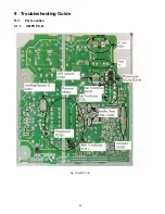
Страница 24: ...24 9 Troubleshooting Guide 9 1 Part Location 9 1 1 SMPS P C B Fig 1 SMPS P C B ...
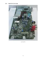
Страница 25: ...25 9 1 2 Main P C B Front side Fig 2 Main P C B ...
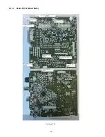
Страница 26: ...26 9 1 3 Main P C B Back Side Fig 3 Main P C B ...
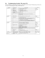
Страница 28: ...28 9 3 D Amp IC Operation Control ...
Страница 33: ...33 11 2 Main Components and P C B Locations ...
Страница 63: ...63 13 Simplified Block Diagram 13 1 Power Block Diagram ...
Страница 72: ...72 ...
Страница 100: ...100 ...
Страница 110: ...110 ...
Страница 114: ...114 ...

