


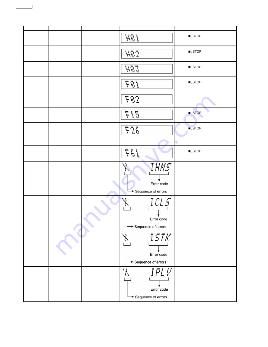
The error code is automatically display after entering into self-diagnostic mode.
Error Code
Diagnosis Contents Description of error
Automatic FL Display
Remarks
H01
Mode SW, plunger
and capstan motor
abnormal
For deck mechanism unit (For deck 1/2).
Press [
] on main unit for
next error.
H02
Rec INH SW
abnormal
For deck mechanism unit (For deck 2).
Press [
] on main unit for
next error.
H03
HALF SW abnormal
For deck mechanism unit (For deck 1/2).
Press [
] on main unit for
next error.
F01
F02
Reel pulse abnormal
TPS error
For deck mechanism unit (For deck 1/2).
Press [
] on main unit for
next error.
F15
RESET SW
abnormal
REST SW: ON is not
detected
within
the
specified time.
For CD unit (For Traverse).
Press [
] on main unit for
next error.
F26
Transmission error
between CD Servo
LSI IC and
microprocessor IC
When set to CD mode,
the sense signal does
not turn “Low”, a fail safe
time
after
system
command transmission
is sent.
For CD unit (For Traverse).
Press [
] on main unit for
next error.
F61
Power Amp IC output
abnormal
Upon
power
on,
PCONT=HIGH,
DCDET=L after checking
LSI.
For power.
Press [
] on main unit for
next error.
IHMS
Cam gear
abnormality
Cam
gear
does
not
rotate
to
“HOME”
position.
For CD changer unit (CRS1).
Press [SINGLE CHANGE] on main unit
for next error.
ICSL
Cam gear/gear units
abnormal
Cam
gear
does
not
rotate to “PLAY” driving
position and hence does
not drive playing tray to
“STOCK” position.
For CD changer unit (CRS1).
Press [SINGLE CHANGE] on main unit
for next error.
ISTK
Drive rack/gear
assembly abnormal
The tray drive rack does
not move to “STOCK”
position. (Tray does not
move
to
“STOCK”
position)
For CD changer unit (CRS1).
Press [SINGLE CHANGE] on main unit
for next error.
IPLY
Drive rack/gear
assembly abnormal
The tray drive rack does
not move to “PLAY”
position. (Tray does not
move to “PLAY” position)
For CD changer unit (CRS1).
Press [SINGLE CHANGE] on main unit
for next error.
18
SA-AK640PL
Содержание SA-AK640PL
Страница 12: ...7 Accessories Remote Control FM Antenna Wire AC Cord AM Loop Antenna 12 SA AK640PL ...
Страница 13: ...8 Operating Instructions Procedures 13 SA AK640PL ...
Страница 14: ...14 SA AK640PL ...
Страница 23: ...10 3 Main Parts Location 23 SA AK640PL ...
Страница 39: ...39 SA AK640PL ...
Страница 41: ...12 2 Checking and Repairing of Transformer P C B 41 SA AK640PL ...
Страница 42: ...12 3 Checking and Repairing of Panel Deck Deck Mechanism P C B 42 SA AK640PL ...
Страница 43: ...12 4 Checking and Repairing of Power P C B 43 SA AK640PL ...
Страница 46: ...Fig 7 13 2 3 Adjustment Point Below is the locations of alignment points on the Main Tuner P C B 46 SA AK640PL ...
Страница 48: ...48 SA AK640PL ...
Страница 49: ...14 2 Power P C B Transformer P C B 49 SA AK640PL ...
Страница 50: ...14 3 Waveform Chart 50 SA AK640PL ...
Страница 51: ...51 SA AK640PL ...
Страница 58: ...58 SA AK640PL ...
Страница 60: ...SA AK640PL 60 ...
Страница 62: ...SA AK640PL 62 ...
Страница 68: ...SA AK640PL 68 ...
Страница 70: ...SA AK640PL 70 ...
Страница 76: ...SA AK640PL 76 ...
Страница 84: ...SA AK640PL 84 ...
Страница 89: ...21 Exploded Views 21 1 Cabinet Parts Location SA AK640PL 89 ...
Страница 90: ...SA AK640PL 90 ...
Страница 91: ...21 2 Deck Mechanism Parts Location RAA4502 S SA AK640PL 91 ...
Страница 92: ...21 3 Packaging SA AK640PL 92 ...


