background image

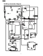
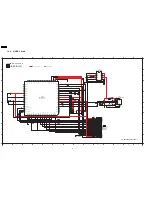
TO

CD SERVO

CIRCUIT

(CN7002)

IN SCHEMATIC

DIAGRAM-1

TO TUNER PACK

J3CCBB000009

TO

USB MODULE CIRCUIT (P901)

IN SCHEMATIC DIAGRAM-12

1

2

3

4

5

6

7

8

9

10

11

12

13

14

I

J

L

M

N

P

O

K

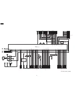
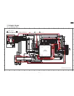
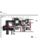
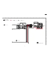
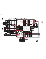
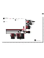
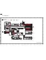
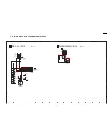
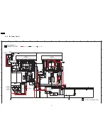
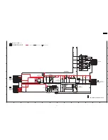
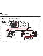
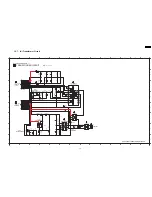
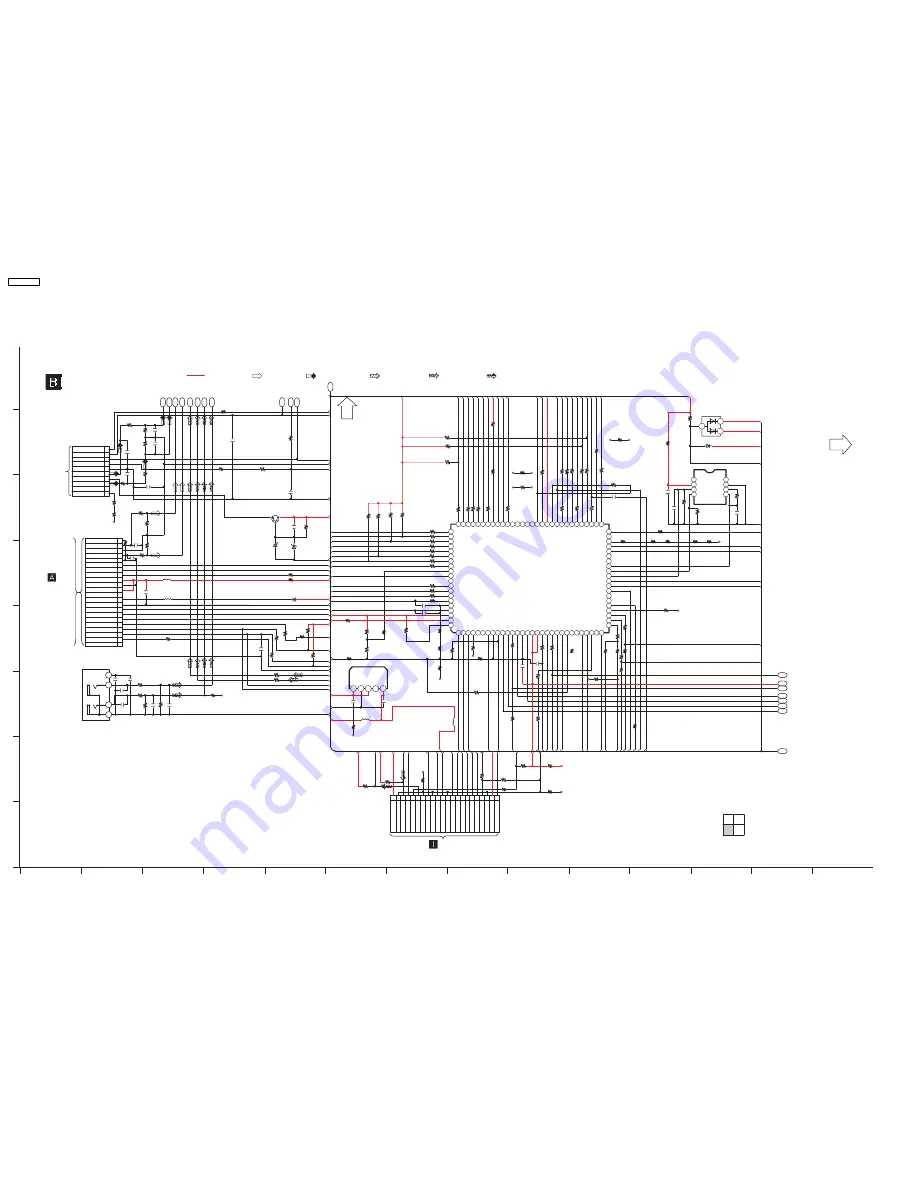
MAIN CIRCUIT

SCHEMATIC DIAGRAM - 4

SA-

AK450PL

MAIN CIRCUIT

1/4

2/4

3/4

4/4

: +B SIGNAL LINE

2

1

5

4

3

NC

OUT

IN

STBY

GND

3

1

2

TO MAIN SECTION (4/4)

TO MAIN SECTION (1/4)

R2812

100K

C18

C19

C21

C23

C24

C25

C26

C27

C28

C29

C20

C22

C10

C11
C12

C13
C14
C15
C16

C17

EE_CS

NC

VCC

GND

NC

EE_DAT

EE_CLK

[81] CD_RST

[82] CLOSE_SW

[83] OPEN_SW

REC

DMT

PL

PHOTO

MTR

VOL_LED

MLD

Vss

FL_CLK

FL_CS

VCC

FL_DOUT

HOME_SW

/RESTSW

MCLK

STAUTS

PAM

CS

MDATA_OUT

PLL_DATA

PLL_CLK

SYNC

Vss

Vcc

Xin

Xcin

Xout

BYTE

LM_1

RMT

/NMI

SW_LVL1

ST_SW

KEY3

PLAY_SW
PLUNGER

CW
CCW

D-PORT

DET1

CNVSS

F_HOP

RDS_CLK

I-POD

LINK

RDS_DAT

D-PORT

DET2

KEY1

DECK AD1

KEY2

AVSS

[97] DECK_AD2

[98] Vref

[99] Avcc

[100] DEMO_SET

BLKCK

Xcout

/RESET

ASP_DAT

SW_LVL2

ASP_CLK

D-PROT_F-SKIP

EE_DAT
EE_CLK

DCDET

PCONT/EFP/CS

MUTE_A

MUTE_DA

EE_CS/EFP/EPM

R3210

R2801

C2821

C2984

R2804

R2825

R2802

R3303

R2808

R2815

R2844

R2816

R2854

R2818

R2845

R2817

R2871

R2873

C2874

C2872

C2871

R2874

R2894

D2813

D2811

R2827

R2828

R2826

R2673

C2674

C2673

R2676

CE
D1

CLK

D0

GND

L-OUT

VSM

FM DET/RDS

CD_GND

L

A_GND

R

CD_GND

ST_IN

ST_CLK

ST_CLK

ST_REQ

ST_REQ

CD_3.3V

CD_GND

LD_SW

TX

+7.5V

U_GND

MCLK

MDATA

MLD

BLKCK

STAT

/RST

/REST_SW

LOADING

VCC

R-OUT

C2678

R2222

R2122

C2221

R2221

C3112

C3113

R2121

C2121

C2675

R2132

Q3601

Q3601

R2131

R2677

R2805

L4001

R3202

R3204

L4000

C4000

C4001

IC4000

IC4000

R3200

R2849

D5V

DGND

USB_SCL

VERIFY_ERROR

USB_IRQ

USB_SDA

DGND

CD_CLK

DGND

CD_STAT

CD_DATA

DGND

STCLK

TIMEOUT.ERROR

STREQ

STIN

CD_MLD

CD_RST

USB_RST

DGND

D3.3V

MMODO.ERROR

R3206

R2839

R2836

R2842

R2838

R2834

R2846

C2986

C2901

C2676

R2232

R2231

C2006

R2922

R2918

R2924

D3101

R2921

C2985

CN2801

R2830

R2843

R2848

R2927

R2151

R2251

R2241

L2901

L2902

R2142

R2242

C2249

C2149

R2141

C2240

C2981 C2983

JK2803

AUX IN

C2140

R2841

R3205

R2850

R2916

R2912

R2914

R2853

R2835

R2833

R2837

R2840

C2954

C2953

C2956

D2603

R3213

R3214

R3212

R3211

100k

100

100p

100p

100

100

10k

100k

100

100

2.2K

100

100

10k

100

10k

22k

22k

330p

0.022u

330p

4.7k

47k

47k

47k

47k

47k

0.01u

100p

10k

0.01u

3.3k

3.3k

3300p

3.3k

220P

220P

3.3k

3300p

100p

3.3k

3.3k

240

10K

4.7K

0

0.1

0.022

4.7K

4.7K

10K

100

100

100

100

100

100k

1000P

0.1u

16V220

SWITCH

3.3k

3.3k

1000P

10k

1K

1K

4.7k

1000P

47k

R2829

47k

R2831

47k

R2832

47k

100

10K

1K

0
0

12k

G0C101JA0052

G0C101JA0052

2.7k

2.7k

100p

100p

12k

1000p

1000p 1000p

1000p

100

100K

10k

4.7K

4.7K

4.7K

100

100

100

100

100

560P

560P

100P

100

100

100

100

U_GND

RMT

BLKCK

CNVSS

H.BASS_LED

VCC

A_GND

FL_CLK

VREF+

FL_DA

FL_CS

ASP_CLK

T_E

M_E

V_E

PLL_CLK

D1

D0

ASP_DA

UP_SENSOR

U_GND

VOL_LED

DMT

CE

BOTTOM_SW

PHOTO

MTR[58]

PL

REC[59]

D-PLAY_PAUSE

VCC

SYNC

U_GND

IDCDET

PCONT

STANDBY

MUTE_D_AMP

MUTE_A

VREF+

+15V

+3.3V

IDCDET

+5V

lRESET

HOME_SW

A_GND

D0

T_GND

+15V

PLL_CLK

D1

CE

+3.3V

DVREF+

T_E

CD_3.3V

USB_RST- UART_CLK

CD_3.3V

U_GND

VREF+

SYS6V

CD_3.3V

MCLK

CD_STAT

MDATA

ST_CLK

ST_REQ

ST_IN

USB_SCL- IPOD_RXD

V_E

USB_SDA- IPOD_TXD

MLD

+5V

CD_RST

+3.3V

CD8.5V

CD_3.3V

U_GND

A_GND

STATUS

BLKCK

+3.3V

MLD

MCLK

MDATA

CLOSE_SW

DECK_AD2

KEY1

VREF+

A_GND

PA_IN_L

PA_IN_R

CD

_RESET

ST_SW

CHG_CW

PLAY_SW

KEY2

CHG_PLR[88]

A_GND

RESTSW

F_HOP

DLINKDET1

LM_1

DLINKDET2

DECK_AD1

KEY3

V_JOG_A

USB_IRQ

M_E

A_GND

A_GND

VCC

MDATA

MLD

STATUS

MCLK

RESTSW

OPEN_SW

CHG_CCW

CD_RESET

USB_IRQ

CD_RST

CD_STAT

ST_IN

B0ACCK000005

B0ADCJ000020

CN3601

2SC3940A0A

D0GB000J008

3.3V REGULATOR

D0GB000J008

C0DBZGC00067

B0EAKM000117

B0BC9R000008

CE

UP_SENSOR

BOTTOM_SW

V.LED_CS

D-PORT_RES2

D-PORT_RES1

[50] STANDBY

[49] XM_PCONT

[48] XM_RST

DO

D1

S/WOOFER

CS

REG

VOL_JOG

D-PORT_PCONT

FL_CS

[31] USB_SDA (TxD)

MMOD0

D-PORT_STOP

H.

BASS_LED

USB_REQ

D-PORT_R-SKIP

XM_DAC_RESET

XM_ANT_REV

XM_RX_IN

VERR

XM_MUTE(BUSY)

[33] USB

XM_I2S_RATE

TERR

CN3200

6

8
9

7

2

1

4
5

3

10

6

5

8
9

11
12

10

18

15

17

16

20

19

13
14

7

2

1

4

3

22

22

1

21

2

3

4

1

6

5

8 9

11 12

10

18

15

17

16

20

19

13 14

7

2

1

4

3

22

21

3 4

2

5

98

94
95

92

91

93

97

96

1

100

99

80

78

76

77

79

87

86

88
89

82

84

83

81

85

90

16

14 15

17

11

13

12

69

67

65 64

66

68

70

51

49

45

47
46

41

44

42

43

48

50

30

39

37

35

32
31

34
33

36

38

40

22 23

20 21

26

28

27

24 25

18 19

53

55

57

62

60 59

61

63

58

56

54

29

52

75

73

71

72

74

9

7

6

8

10

7

8

5

4

3

1
2

6

IC2871

E-EPROM IC

(NOT SUPPLIED)

IC2801

C2CBYY000423

MICROPROCESSOR

[32] USB_SDA (RxD)

IC2871

: CD SIGNAL LINE

USB

: AUX SIGNAL LINE

: MAIN SIGNAL LINE

: FM/AM SIGNAL LINE

: USB SIGNAL LINE

USB_SDA-IPOD_TXD

USB_SDA

USB_SCL-IPOD_RXD

USB_SCL

USB_RST-UART_CLK

USB_RST

W599

0

W664

0

W629

0

W658

0

W612

0

W638

0

W620

0

W603

0

W639

0

W608

0

W633

0

W679

0

W647

0

W577

0

W610

0

W607

0

W598

0

W606

0

W676

0

W602

0

W635

0

W663

0

W614

0

W613

0

W616

0

W625

0

W637

0

W624

0

W655

0

W643

0

W659

0

W644

0

W657

0

W636

0

W662

0

W634

0

W649

0

W628

0

W642

0

W601

0

K3201

0

W609

0

W632

0

W617

0

W645

0

W660

0

W593

0

W646

0

W626

0

W653

0

SA-AK450PL

68

Содержание SA-AK450PL

Страница 1: ... and distribution is a violation of law SA AK450PL Colour K Black Type 87 5 to 108 0 MHz 100 kHz steps Sensitivity 4 0 µV IHF S N 26 dB 2 2 µV Antenna terminal s 75 Ω unbalanced Amplitude Modulation AM Frequency range 520 to 1710 kHz 10 kHz step Sensitivity S N 20 dB at 1000 kHz 560 µV m Audio performance Amplifier Input sensitivity Input impedance Aux 250 mV 14 7 kΩ Music Port input jack Terminal...

Страница 2: ...Precaution of laser diode 9 1 HDD 2 USB MP3 Player Digital audio player 3 USB Thumbdrives Supported audio file format MP3 bit rate USB memory port Maximum current 500 mA Bit rate MP3 32 kbps to 320 kbps Sampling frequency MP3 32 kHz 44 1 kHz 48 kHz Audio output MP3 Number of channels 2 channel Frequency response MP3 20 Hz to 20 kHz 0 1 0 dB S N Ratio USB unit out 93 28 dB n GENERAL Power supply AC...

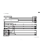
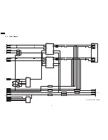
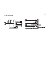
Страница 3: ...on Check with Cassette Tape 46 13 2 Operation Check without Cassette Tape 46 14 Measurement And Adjustments 48 14 1 Cassette Deck Section 48 15 Voltage and Waveform Chart 50 15 1 CD Servo P C B 50 15 2 Deck P C B 50 15 3 Main P C B 51 15 4 Panel P C B 51 15 5 Power P C B Transformer P C B 52 15 6 Waveform Chart 53 16 Wiring Connection Diagram 54 17 Block Diagram 55 17 1 CD Servo Diagram 55 17 2 De...

Страница 4: ...should be between 1MΩ and 5 2MΩ When the exposed metal does not have a return path to the chassis the reading must be 1 1 2 Leakage Current Hot Check See Figure 1 1 Plug the AC cord directly into the AC outlet Do not use an isolation transformer for this check 2 Connect a 1 5kΩ 10 watts resistor in parallel with a 0 15µF capacitor between each exposed metallic part on the set and a good earth grou...

Страница 5: ...to prevent shock fire or other hazards Do not modify the original design without permission of manufacturer Table 1 Reference No Part No Part name Description Remarks L5950 ELF15N035AN LINE FILTER T5950 G4CYAYY00147 MAIN TRANSFORMER T5951 G4C2AAJ00005 SUB TRANSFORMER Z5950 ERZV10V511CS ZENER RL5950 K6B1AEA00015 POWER RELAY F1 K5D402APA008 FUSE FP5920 K5G702A00009 FUSE PROTECTOR FP5940 K5G702Z00004...

Страница 6: ...Do not remove a replacement ES device from its protective package until immediately before you are ready to install it Most replacement ES devices are packaged with leads electrically shorted together by conductive foam aluminium foil or comparable conductive material 7 Immediately before removing the protective material from the leads of a replacement ES device touch the protective material to th...

Страница 7: ...short pin finish the job in as short time as possible 4 Do not turn the variable resistor for laser power adjustment It is pre adjusted during production time Grounding for electrostatic breakdown prevention 1 Human body grounding Use the anti static wrist strap to discharge the static electricity from your body 2 Work table grounding Put a conductive material sheet or steel sheet on the area wher...

Страница 8: ...8 SA AK450PL ...

Страница 9: ... the preset variable resistor on the optical pickup lens 4 Do not disassemble the optical optical pickup unit 5 If the optical pickup is replaced use the manufacturer s specified replacement pickup only 6 Use of control or adjustments or performance of procedures other than those specified herein may result in hazardous radiation exposure CAUTION THIS PRODUCT UTILIZES A LASER USE OF CONTROLS OR AD...

Страница 10: ...Lead Free Solder PbF The lead free solder has to be used when repairing the equipment for which the lead free solder is used Definition The letter of PbF is printed on the PCB using the lead free solder To put lead free solder it should be well molten and mixed with the original lead free solder Remove the remaining lead free solder on the PCB cleanly for soldering of the new IC Since the melting ...

Страница 11: ...6 Accessories Remote Control FM Antenna Wire AC Cord AM Loop Antenna 11 SA AK450PL ...

Страница 12: ...7 Operating Instructions Procedures 7 1 Main Unit Key Buttons Operations 12 SA AK450PL ...

Страница 13: ...7 2 Remote Control Key Buttons Operations 13 SA AK450PL ...

Страница 14: ...8 New Features 8 1 Using the Music Port and USB Mass Storage Class Device This feature enables you to enjoy music from a portable audio equipment 14 SA AK450PL ...

Страница 15: ...With reference to page 15 of the operating instruction manual With reference to page 16 of the operating instruction manual 15 SA AK450PL ...

Страница 16: ...re information Muting Clock Setting Refer to the section 9 2 for more information 0 Tape Eject Test Refer to the section 9 2 for more information DIMMER All segment display for the FL Refer to the section 9 2 for more information DISC CRS1 Inspection Refer to the section 9 2 for more information 7 Volume 50 Setting check 8 Volume 41 Setting check 9 Volume 35 Setting check Volume 0 Setting check PR...

Страница 17: ...ment result for FLOCK TLOCK and CLVS FLOCK Focus Lock TLOCK Traverse Lock CLVS Constant Linear Velocity Speed In CD Test Mode 1 Press 0 button on the remote control To exit press button on main unit or remote control CD Changer Reliability Test CRS1 To determine the reliability of CD Changer Unit For more information refer to section 9 3 In Self Diagnostic Mode 1 Select for CD mode 2 Press button ...

Страница 18: ...this mode Step 1 Enter into Doctor mode for more information refer to section 9 2 on the key operation to enter into this mode Step 2 By pressing STOP button on main unit followed by 4 and 7 on remote control Check for firmware version and EEPROM checksum When entering into DOCTOR MODE the firmware version and checksum data of EEPROM if applicable will appear on FL display Below is the information...

Страница 19: ...s subject to change which would be updated accordingly ROM correction checksum refers to the HEX code that is displayed upon key buttons pressed if an EEPROM is loaded in the unit 9 3 Reliability Test Mode CRS1 Mechanism Below is the process flow chart of ageing for the CD changer unit CRS1 19 SA AK450PL ...

Страница 20: ...Function refer Section 9 2 provides information on any problems occuring for the unit and its respective components by displaying the error codes These error code such as U H and F are stored in memory and held unless it is cleared 20 SA AK450PL ...

Страница 21: ...ween CD Servo LSI IC and microprocessor IC When set to CD mode the sense signal does not turn Low a fail safe time after system command transmission is sent For CD unit For Traverse Press on main unit for next error IHMS Cam gear abnormality Cam gear does not rotate to HOME position For CD changer unit CRS1 Press SINGLE CHANGE on main unit for next error ICSL Cam gear gear units abnormal Cam gear ...

Страница 22: ...ll automatically close all trays after the time out by the microprocessor During this time when it fails the error code will appear For CD changer unit CRS1 Press SINGLE CHANGE on main unit for next error F2NG Fail safe mode For open close tray unit s When the tray close operation is performed it fails to close It will automatically open all trays after the time out by the microprocessor During th...

Страница 23: ...ode memorized In CRS1 Self Diagnostic mode press SINGLE CHANGE to display subsequence error code It shall repeat after reaching error no 5 e g 1 _ _ _ _ I H M S SINGLE CHANGE 2 _ _ _ _ I T O P SINGLE CHANGE 3 _ _ _ _ H O M E SINGLE CHANGE 4 _ _ _ _ L O A D SINGLE CHANGE 5 _ _ _ _ _ U D D SINGLE CHANGE 3 To clear the error code memory In CRS1 Self Diagnostic mode long press SINGLE CHANGE key 2s or ...

Страница 24: ...s or replacement reverse the respective procedures Special reassembly procedures are described only when required 3 Select items from the following index when checks or replacement are required 4 Refer to the Parts No on the page of Parts Location and Replacement Parts List Section 24 if necessary Caution After replacing of CD Changer Unit ageing test is necessary Please confirm operation for CD C...

Страница 25: ...hart The following chart is the procedure for disassembling the casing and inside parts for internal inspection when carrying out the servicing To assemble the unit reverse the steps shown in the chart as below 25 SA AK450PL ...

Страница 26: ...10 3 Main Parts Location 26 SA AK450PL ...

Страница 27: ... Push the top cabinet backwards to release catches Step 5 Remove top cabinet Step 1 Remove 1 screw at rear panel Step 2 Detach the FFC cables CN2801 CN2805 at Main P C B Step 3 Release the claws outwards on both ends 10 4 Disassembly of Top Cabinet 10 5 Disassembly of CD Changer Unit CRS1 Follow the Step 1 Step 5 of Item 10 4 27 SA AK450PL ...

Страница 28: ...screws Step 6 Remove the Mecha Chassis Note For disassembly assembly of traverse unit please refer to section 10 16 of this service manual Please refer to original Service Manual for the Disassembly and Assembly of the CD Changer Unit CRS1 10 6 Disassembly of Rear Panel Follow the Step 1 Step 5 of Item 10 4 28 SA AK450PL ...

Страница 29: ...Step 2 Detach cable CN2810 at Main P C B Step 3 Detach FFC cables CN2801 CN2805 at Main P C B Step 4 Remove rear panel 29 SA AK450PL ...

Страница 30: ...transformer to bottom chassis Step 3 Push the Transformer P C B backwards to remove it Step 2 Remove Main P C B Follow the Step 1 Step 5 of Item 10 4 Follow the Step 1 Step 4 of Item 10 5 Follow the Step 1 Step 4 of Item 10 6 10 8 Disassembly of Transformer P C B Follow the Step 1 Step 5 of Item 10 4 Follow the Step 1 Step 4 of Item 10 5 Follow the Step 1 Step 4 of Item 10 6 30 SA AK450PL ...

Страница 31: ... 3 Remove IC5301 from heat sink unit Note For disassembly of IC5101 Q5101 Q5102 Q5111 and Q5112 repeat Step 1 to Step 2 For information IC5101 Q5101 Q5102 Q5111 and Q5112 does not have IC clip Replacement of IC5501 Step 1 Flip the Power P C B over and desolder the pins of IC5501 Step 2 Twist the heat sink leg as arrow shown 10 9 Disassembly of Power P C B Follow the Step 1 Step 5 of Item 10 4 Foll...

Страница 32: ... Step 2 Detach cable CN5951 at Transformer P C B Step 3 Bent the front panel unit slightly forward as arrow shown Caution During assembly of the heat sink sub assembly with IC5501 all soldering points is touch up to avoid dry joints Step 4 Release 2 claws outwards 10 10 Disassembly of Front Panel Unit Follow the Step 1 Step 5 of Item 10 4 Follow the Step 1 Step 5 of Item 10 5 32 SA AK450PL ...

Страница 33: ... at bottom of front panel at 2 catches one on each side of bottom chassis to be aligned to front panel s slot Assembly is secured upon hearing clicking sound Step 4 Remove Panel P C B 10 11 1 Disassembly of Lid Step 1 Lift the spring sideward 10 11 Disassembly for Panel P C B Follow the Step 1 Step 5 of Item 10 4 Follow the Step 1 Step 4 of Item 10 5 Follow the Step 1 Step 5 of Item 10 10 33 SA AK...

Страница 34: ...ow shown Step 2 Remove Lid Note Do not misplace the spring 10 12 Disassembly of Tact Switch P C B Follow the Step 1 Step 5 of Item 10 4 Follow the Step 1 Step 4 of Item 10 5 Follow the Step 1 Step 5 of Item 10 10 10 13 Disassembly of USB P C B Follow the Step 1 Step 5 of Item 10 4 Follow the Step 1 Step 4 of Item 10 5 Follow the Step 1 Step 5 of Item 10 10 34 SA AK450PL ...

Страница 35: ... then remove it in the direction of arrow 2 Note For disassembly of parts for deck mechanism unit refer to Section 10 17 10 14 Disassembly of Deck mechanism unit Follow the Step 1 Step 5 of Item 10 4 Follow the Step 1 Step 4 of Item 10 5 Follow the Step 1 Step 5 of Item 10 10 10 15 Disassembly of Deck P C B Follow the Step 1 Step 5 of Item 10 4 Follow the Step 1 Step 4 of Item 10 5 Follow the Step...

Страница 36: ...ay In STOCK position for CRS1 Service Manual order no MD0509368C0 Step 1 Press and hold the plunger lever and rotate the gear as arrows shown until it stop Step 3 Remove Deck P C B Step 2 Push the traverse slide plate as arrow shown to release the traverse unit Caution Do not exert strong force on the traverse slide plate 10 16 Disassembly of Traverse Unit Follow the Step 1 Step 5 of Item 10 4 Fol...

Страница 37: ...unit Step 2 Push the traverse slide plate as arrow shown to lock the traverse unit 10 17 Disassembly for Deck Mechanism Follow the Step 1 Step 4 of Item 10 4 Follow the Step 1 Step 4 of Item 10 5 Follow the Step 1 Step 5 of Item 10 10 Follow the Step 1 Step 3 of Item 10 14 Follow the Step 1 Step 3 of Item 10 15 37 SA AK450PL ...

Страница 38: ...10 17 1 Replacement of Pinch Roller and Head Block 38 SA AK450PL ...

Страница 39: ...10 17 2 Replacement of Motor Capstan Belt A Capstan Belt B and Winding Belt 39 SA AK450PL ...

Страница 40: ...tep 4 Remove Deck Mechanism P C B 10 18 Disassembly of Deck Mechanism P C B Follow the Step 1 Step 4 of Item 10 4 Follow the Step 1 Step 4 of Item 10 5 Follow the Step 1 Step 5 of Item 10 10 Follow the Step 1 Step 3 of Item 10 14 Follow the Step 1 Step 3 of Item 10 15 40 SA AK450PL ...

Страница 41: ...ywheel F in the direction of the arrow to remove it Step 2 Remove spring and push the cassette lid in the direction of arrows 10 19 Disassembly of cassette lid Follow the Step 1 Step 4 of Item 10 4 Follow the Step 1 Step 4 of Item 10 5 Follow the Step 1 Step 5 of Item 10 10 Follow the Step 1 Step 3 of Item 10 14 10 20 Rectification for tape jam problem Follow the Step 1 Step 5 of Item 10 4 41 SA A...

Страница 42: ...Step 2 Push the lever upward and open the cassette lid Remove the cassette tape Note Follow 10 19 Disassembly of cassette lid Step1 to Step 3 Remove the cassette tape 42 SA AK450PL ...

Страница 43: ...d Tools Service Tools Extension FFC A Deck P C B Main P C B REEX0485 14 Pins 12 Service Positions Note For description of the disassembly procedures see the Section 10 12 1 Checking and Repairing of Main P C B 43 SA AK450PL ...

Страница 44: ...12 2 Checking and Repairing of Transformer P C B 12 3 Checking and Repairing of Panel Deck Deck Mechanism P C B 44 SA AK450PL ...

Страница 45: ...12 4 Checking and Repairing of Power P C B 45 SA AK450PL ...

Страница 46: ...al timing at STOP mode ON approx 200msec e REV REW Supply the plunger power in a flash at REV PLAY mode ON approx 50msec f STOP Supply the plunger power in a flash at FF mode ON approx 50msec Repeat the operation FWD PLAY Note Other operation may start if a timing of supplying the plunger power is missed 13 1 1 Connection Status between Mechanism and Power Supply Motor Plunger 13 1 2 Operative Par...

Страница 47: ...47 SA AK450PL ...

Страница 48: ...g 2 Remove 4 screws from the mechanism unit to disassemble under 10 14 Disassembly of Deck Mechanism Unit 3 Connect the headphone jack output jig Fig 8 to headphone jack Fig 8 Fig 9 14 1 4 Tape Speed Adjustment Normal speed adjustment only during forward playback Product reference value 3 000 90Hz 1 Connect a frequency indicator Fig 10 2 Playback the middle portion of the test tape QZZCWAT 3 Adjus...

Страница 49: ...he recording mode Repeat pressing the buttons till the recording pause mode is activated 5 Check that the output level is within the standard range Standard Range 16 3mV Fig 12 14 1 6 Bias Frequency Check 1 Connect a digital frequency counter Fig 13 2 Set the function to TAPE position 3 Insert a normal blank cassette tape QZZCRA and press REC mode on main unit 4 Check that the output frequency is ...

Страница 50: ...bed herein shall be regarded as reference information when probing defect point because it may differ from an actual measuring value due to difference of Measuring instrument and its measuring condition and product itself 15 1 CD Servo P C B 15 2 Deck P C B 50 SA AK450PL ...

Страница 51: ...15 3 Main P C B 15 4 Panel P C B 51 SA AK450PL ...

Страница 52: ...15 5 Power P C B Transformer P C B 52 SA AK450PL ...

Страница 53: ...15 6 Waveform Chart 53 SA AK450PL ...

Страница 54: ...P C B SOLDER SIDE I USB P C B SOLDER SIDE SIDE B PbF PbF PbF PbF PbF PbF 1 21 2 20 9 1 CN2810 2 1 CN2801 21 1 22 2 CN3200 21 1 22 2 CN2805 15 1 14 2 CN2806 30 2 29 1 CN2803 H6555 JK6501 VR6511 JK6551 20 2 9 1 21 1 CN2808 12 1 CN2809 12 1 CN3601 JK2803 10 1 B MAIN P C B SOLDER SIDE E POWER P C B SOLDER SIDE PbF PbF PbF JW6002 Z6481 JK6751 1 10 CN5951 CN5950 1 9 CN6601 2 30 1 29 9 1 H5104 9 1 JK5101...

Страница 55: ...41 49 48 45 43 32 34 44 22 21 24 25 23 29 30 66 57 AVSS1 TX SRVMON1 SRVMON0 NTEST NRST AVDD2 AVSS2 ARFFB ARFF ARFOUT ARFDC RFOUT RFIN CENV CTRCRS OSCIN VREF RFENV PC SPOUT TRVP TRP FOP LD PD A B C D E F NSRVMONON REGON MDATA ARFIN IREF DSLF PLLF PLLFO TXTCK SBCK PRAMVDD33 PRAMVSS33 D0 D15 A0 A11 BA0 BA1 TXTD DQSY SUBC TXNCLDCK BLKCK FLAG 65 71 20 18 83 92 94 99 1 7 11 15 16 17 NWE NCAS 8 9 63 64 6...

Страница 56: ...6K DECK R P IC IC1000 C1AA00000612 ANALOG SWITCH IC971 CNB13030R2AU PHOTO INTERUPTOR L1301 Q1317 SWITCH Q1316 SWITCH Q1314 SWITCH 9V Q1315 SWITCH Q1317 SWITCH Q1304 SWITCH Q1101 MUTE SWITCH Q1304 Q1303 SWITCH Q1309 Q1310 BIAS SWITCH 9 22 15 8 1 3 5 2 4 19 4 16 17 6 DECK 2 HEAD RCH DECK 2 ERASE HEAD DECK 1 B HEAD LCH MUTE SWITCH Q1302 MUTE SWITCH DRIVER DECK MECHANISM CIRCUIT TO MAIN 1 2 TO MAIN 2 ...

Страница 57: ...SWITCH Q2417 MUTE SWITCH HPF LPF Q2511 MUTE SWITCH DRIVER CN2809 CN5102 12 CN2809 CN5102 5 CN2809 CN5102 6 CN2809 CN5102 8 CN2809 CN5102 9 CN2809 CN5102 4 CN2803 CN1305 13 CN2803 CN1305 12 CN2806 CN6601 25 CN2806 CN6601 27 1 IN L1 2 IN R1 5 IN L3 6 IN R3 12 11 IN L6 IN R6 7 IN L4 8 IN R4 56 OP IN 3 IN L2 4 IN R2 IC2803 C1BB00001121 AUDIO SOUND PROCESSOR 39 40 CLK DATA IDCDET ASPCLK ASPDA LM 1 MUTE...

Страница 58: ...CN3601 7 CN3601 4 CN3601 3 CN3601 2 CN3601 1 CN2805 4 D2937 D2941 17 16 15 CN2801 CN7002 6 CN2801 CN7002 7 CN2801 CN7002 8 FROM USB CN3200 P901 18 CN3200 P901 19 CN3200 P901 13 CN3200 P901 15 CN3200 P901 16 CN3200 P901 17 CN3200 P901 8 CN3200 P901 10 CN3200 P901 11 CN3200 P901 5 26 27 1 15 13 10 11 78 77 76 19 75 81 79 50 47 46 3 5 4 41 42 43 94 20 18 93 71 90 92 72 70 51 88 54 55 87 82 83 86 80 8...

Страница 59: ...JW6601 JW6002 3 JW6601 JW6002 7 JW6601 JW6002 10 JW6601 JW6002 9 JW6601 JW6002 8 JW6601 JW6002 2 JW6601 JW6002 4 CN6601 CN2806 3 CN6601 CN2806 11 CN6601 CN2806 13 H6555 CN5951 7 FL6602 A2BD00000171 FL DISPLAY IC6601 C0HBB0000057 FL DRIVER 14 29 25 40 1 44 FL1 FL2 31 41 5 11 Z6481 JK6501 MIC 7 9 8 DIN STB CLK QR6457 LED DRIVE Q6501 MIC AMP S6201 S6207 Q6502 MIC AMP VR6511 MIC VOLUME JK6751 M PORT J...

Страница 60: ...ER LCH LOW X5201 X5202 IC5301 C1AA00000755 2CH DIGITAL AMP 2 3 IN1 OUT1 10 OUT2 14 VDDA1 20 VSSA1 18 IN1 21 22 IN2 IN2 23 MODE 1 OSC 1 OSC Q5153 IC5401 C1AA00000755 2CH DIGITAL AMP 2 3 IN1 IN1 21 22 IN2 IN2 23 MODE IC5201 C0JBAB000011 LOGIC IC5101 C0DAZYY00005 REGULATOR IC 1 10 2 3 6 5 4 2 5 6V VCC 3 3V CTRL 1 5 MODE SWITCH Q5201 FREQUENCY HOPPING SWITCH Q5202 D5130 D5126 FREQUENCY HOPPING SWITCH ...

Страница 61: ... D D USB CONNECTOR P903 VBUS D5V TO MAIN 2 2 IC951 C0DBZYE00002 VOLTAGE REGULATOR 6 7 8 VDD CTRL FLAG 2 4 5 OUT IC900 MNZSFB5KJM1 USB CONTROLLER IC 12 11 NRST 14 CD_RST 8 CD_MLD 64 STIN 61 STREQ 54 TERR 51 STCLK 59 CD_DATA 58 CD_STAT 57 CD_CLK 56 47 OSC0 OSC1 4 USBD 6 USBD X900 I2C_REQ WR_START TO POWER TO PANEL T5950 T5951 MAIN TRANSFORMER SUB TRANSFORMER Q5951 VOLTAGE REGULATOR Q5950 VOLTAGE REG...

Страница 62: ...SA AK450PL 62 ...

Страница 63: ... Volume jog VR6511 VR Mic Volume jog Importance safety notice Components identified by mark have special characteristics important for safety Furthermore special parts which have purposes of fire retardant resistors high quality sound capacitors low noise resistors etc are used When replacing any of components be sure to use only manufacturer s specified parts shown in the parts list Resistor Unit...

Страница 64: ...64 SA AK450PL ...

Страница 65: ...BA5948FPE2 4 CH DRIVE IC MLD 7 5V MCLK MDATA RST STAT BLKCK PGND 3 3V ST_IN TX LD SW DGND ST_CLK AGND AGND DGND ST_REQ RESET_SW LCH OUT RCH OUT LOADING A9 A11 TRP TRVP BA1 A0 A2 A4 A6 A8 A7 A5 A3 A1 A10 NWE BA0 PC NRAS NCAS PRAMVDD15 PRAMVDD33 PRAMVSS33 SPOUT F A B E GND T F F T LPD VREF LD GND GND GUARD GND GUARD LD VCC 6 5 8 9 10 12 11 7 2 1 4 3 14 13 16 15 PVCC1 D4 D1 PVCC2 NC NC NC NC NC NC NC...

Страница 66: ... C2194 R2193 R2194 C2173 C2174 R2173 C2171 R2172 C2172 C2192 C2193 D2503 R2674 VOLTAGE REGULATOR CN2803 R2103 R2672 C2501 R2203 C2311 C2411 R2412 R2312 R2355 270K C2342 1u R2508 R2510 R2271 R2511 C2585 D2583 C2583 R2584 R2586 R2587 R2585 C2584 C2588 C2273 C2274 C2402 C2401 C2272 R2273 R2509 C2511 R2512 C2701 R2411 C2442 R2413 Q2411 R2313 R2311 Q2311 R2701 R2702 C2242 C2142 1K 16V100 1u 3 3k 1u 1 5...

Страница 67: ...5 C2331 R2323 C2323 C2325 R2431 C2433 R2321 R2318 R2435 R2329 C2321 Q2317 C2443 R2456 R2356 C2343 R2416 R2423 C2423 R2421 C2425 R2418 Q2417 R2429 C2421 R2417 0 0 1k 1u 10K 1u 68k 68k 47p 1K 1u 10p 15k 10K 10K 15k 68k 47p 50V2 2 10K 68K 10p 1u 2 2k 18k 0 1u 15k 15k 1k 4700P 39k 0 015 16V10 16V10 0 1u 0 100k 4700P C2431 1k 3 3K 1 1 0 47u 180k 180k 0 47u 2 2k 39k 0 015 0 100k 3 3K 18k REC_L REF_L A_G...

Страница 68: ...1K 1K 4 7k 1000P 47k R2829 47k R2831 47k R2832 47k 100 10K 1K 0 0 12k G0C101JA0052 G0C101JA0052 2 7k 2 7k 100p 100p 12k 1000p 1000p 1000p 1000p 100 100K 10k 4 7K 4 7K 4 7K 100 100 100 100 100 560P 560P 100P 100 100 100 100 U_GND RMT BLKCK CNVSS H BASS_LED VCC A_GND FL_CLK VREF FL_DA FL_CS ASP_CLK T_E M_E V_E PLL_CLK D1 D0 ASP_DA UP_SENSOR U_GND VOL_LED DMT CE BOTTOM_SW PHOTO MTR 58 PL REC 59 D PLA...

Страница 69: ... 47K 10V220u 47K 47k 22k 6 3V470 1u 0 1u 220 1M 3 3 0 1u 27 100 56k 6 3V100 5 6K 10K 10k 820k 0 1u TO FAN 4 7K 100P MOT_12V PA_IN_L MIC A_GND 15V A_GND HP_L MOT_12V U_GND CHG_CW CLOSE_SW OPEN_SW A_GND UP_SENSOR PLAY_SW 3 3V OME_SW CD8 5V ST_SW CHG_CCW BOTTOM_SW CHG_PLR 88 HP_R 3 3V U_GND U_GND FL_CLK H BASS_LED FL_CS FL_DA KEY2 RMT VREF PCONT SYS6V SYNC KEY1 U_GND KEY3 PA_IN_R MOT_12V A_GND V_JOG_...

Страница 70: ...EY1_IN PA_SW GR1 P1 P2 P3 P0 VREF VJOG_A KEY3 MOT12V GND2 H BASS_LED KEY3_2 VOL_LED KEY1_OUT KEY1_IN 3 3V GR10 SG2 SG2 SG1 SG1 GR2 GR11 GR1 GR7 GR9 GR8 GR6 GR4 GR3 GR5 GR2 GR1 VDD VDD KEY1_OUT GND2 GND2 C6504 R6504 R6104 S6103 R6103 S6102 R6505 R6105 S6104 Q6501 C6751 C6752 C6508 C6508 C6753 Q6502 D6458 R6458 C6635 D6301 B0ACCK000005 C6632 C6552 C6553 D6635 R6632 R6631 H6555 R6763 R6753 R6751 C655...

Страница 71: ...IAGRAM 10 9 8 7 6 5 4 3 2 1 CS971 PL MODE HALF PL_GND PHOTO_T RECINH_F VREF VREF CR02 5 3 2 1 4 10 8 7 6 9 R6303 R6302 S6302 R6304 S6303 K6104 D6461 B0BC8R100004 D6462 B3AEA0000074 VOL LED D6464 D6464 D0GBR00JA008 R6457 S6301 R6399 R6106 R6491 R6108 S6108 S6106 R6107 R6305 S6304 R6494 R6307 S6309 S6307 S6308 R6308 R6309 R6310 R6306 S6305 S6306 C6491 C6492 R6492 KEY3_2 KEY3 MOT10V VJOG_A VOL_LED ST...

Страница 72: ...TE_F MODE AGND AGND 5V 5V PCONT 5V AGND LO_R F_HOP AGND AGND AGND AGND AGND AGND AGND AGND LO_L HI_L AGND AGND 1M 1M 1M 0 015u 220K 150K 100K 100K 390K R5112 390K 10V220u 1000P 10K 0 1u 0 47u 10 10 10 0 1u 220P 0 1u 0 1u 220P 220P 220P 10 22 0 0 1u 0 0 1u 0 1u 0 1u 0 47u 5 6K 5 6K 0 47u 1K 0 47u 1K 100 100 1000P 5 6K 1K 1K 0 1u 220P 0 015u 1M 330P 0 47u 0 47u 0 1u 0 1u 0 1u 0 1u H2A415300001 H2A37...

Страница 73: ...ET XM5 3V MUTE_F 9V MOTOR12V CD3 3V PCONT 5V AGND 15V PCONT MOTOR12V 0 1u 100V10u 4 7 150K REGULATOR IC 2 2 35V1000 1K 10K 100V10 0 1u 63V1000u 0 1u 2 2K 35V1000 100P 100P 2 2 2 2 50V33 330 0 01u 10K 1 2K 2 2 0 01u 470 25V100u 0 25V100 25V100u 560 22K 0 1u 10K 1K 47 63V1000u 1 8 10K 0 1u 0 1u 0 1u 6 3V100 6 3V100 LL LL LEFT HIGH RIGHT LOW RIGHT LOW RIGHT HIGH RIGHT HIGH LEFT LOW LEFT LOW LEFT HIGH...

Страница 74: ... R1334 22K R1333 4 7 R1327 4 7K R1335 1 5K Q1317 B1ABGC000005 BEATPROOF LEVEL SWITCH R1337 10K Q1312 B1ABCF000011 SWITCH C1314 2200P C1317 1000P C1312 3300P C1318 0 047 R1330 4 7 Q1309 Q1310 B1AAGC000006 BIAS SWITCH Q1309 C1316 1000P RECH1 L1302 G0C470JA0052 D1301 B0ACCK000005 C1319 16V100 R1329 4 7K R1328 15K Q1310 Q1317 C1321 4700P C1202 470P C1201 50V1 C1203 16V100 C1221 1000P R1202 1 5K C1207 ...

Страница 75: ...957 Q5950 C5963 D5958 D5959 CN5950 C5920 C5940 D5960 C5956 FP5920 FP5940 C5957 R5961 R5960 C5958 R5963 D5966 C5951 D5962 D5964 R5952 FP5950 R5951 R5950 D5956 C5959 D5954 D5950 D5951 D5957 D5955 D5961 D5952 D5953 C5955 C5960 C5950 D5963 R5953 C5954 C5961 C5962 Q5952 10V47 0 01u 10K 10K 4 7 47 7A 7A 10 150 4 7K 0 01u 82 0 01u 4 7K 3 3K 3 3M 0 01u 22u 0 1u 150 0 01 10V220 10V220 B0AAFK000004 B1AACF00...

Страница 76: ...3 54 52 57 62 63 61 19 18 20 3 2 5 4 6 8 7 1 64 15 16 9 13 10 12 11 14 17 22 21 59 60 IC900 MNZSFB5KJM1 USB CONTROLLER IC 0 1 C913 DGND D5V NRST P01 P04 DGND P03 STCLK P91 SBIO P81 D8 P73 D5 P00 P02 P66 D0 P72 D4 P70 D2 P71 D3 P75 D7 D3 3V VSS P82 D9 DGND D1 8V VDDI VDD33 TERR P21 NCE0 VSS CD_CLK CD_STAT STREQ PD4 NCE2 CD_DATA P77 NRE VERR VDD5 I2C_REQ WR_START I2C_CLK WR_END I2C_DATA ERROR DGND P...

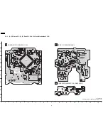
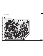
Страница 77: ...20 Printed Circuit Board Note Circuit board diagrams may be modified at any time with the development of new technology SA AK450PL 77 ...

Страница 78: ... SOLENOID 3 2 1 4 PL W1904 W1932 W1902 W1931 W1903 W1933 W1907 W1905 W1947 W1946 W1942 W1945 W1951 W1935 W1909 W1977 W1912 W1921 W1917 W1916 W1911 W1913 W1975 W1948 W1934 W1914 W1915 W1906 W1920 W1976 W1941 W1908 W1918 CP1301 TO R P HEAD C1103 C1106 C1109 C1304 C1201 C1203 C1319 C1320 C1324 C1311 C1305 C1206 C1209 C1301 C1208 C1310 C1101 C1308 Q1309 Q1316 Q1315 L1302 R1330 R1333 R1309 W1910 W1938 ...

Страница 79: ...379 W380 W469 W467 W428 W218 W422 W423 W424 W427 W121 W239 W362 W288 W419 W238 W650 W627 W652 W212 W628 W660 W211 W155 W366 W365 W154 W662 W299 W636 W298 W372 W371 W659 W370 W429 W634 W657 W615 W648 R2937 R2936 W625 W616 W637 W632 W649 W611 W425 W127 W210 W209 W301 W213 W214 W214 W215 W346 W347 W405 W447 W420 W446 W363 W202 C4000 W203 W126 W465 W341 W630 W640 C4001 W676 R2802 R2801 R2811 R2586 R32...

Страница 80: ...W859 W818 9 10 2 4 5 6 7 8 3 W908 W907 C6551 R6204 R6206 R6207 W924 W1011 W1012 W911 W909 W905 R6605 C6603 C6602 C6604 R6604 C6601 W915 W914 D6635 W925 D6301 R6763 R6753 R6754 R6458 C6636 C6753 R6751 W1005 W1002 W1001 R6601 R6603 R6602 R6102 R6105 R6103 R6104 R6209 R6208 R6199 W926 W904 R6481 R6493 R6203 C6553 SENSOR HEADPHONE MUSIC PORT 0109A 0109A R6632 QR6464 QR6463 QR6462 QR6461 Q6501 VR6511 M...

Страница 81: ...C6492 C6491 R6492 R6491 R6302 R6303 R6108 0109A 0109A VR6491 VOLUME W752 IC900 L900 IC951 0101A 0101A C915 C906 X900 C953 P903 C904 C931 P901 0101A 0101A USB LB930 LB852 R955 C952 R954 LB952 R972 C913 LB932 LB933 LB934 LB935 LB840 LB843 LB841 LB936 LB938 C903 R914 LB845 LB846 LB848 R903 LB850 C901 C902 C905 C907 R901 C908 R904 R902 R971 C914 R952 R953 LB951 R951 R957 R950 C951 R906 C912 C911 D6461...

Страница 82: ...1 L5401 Q5102 Q5101 E5101 IC5301 W737 C5115 W671 W733 D5101 C5101 R5101 C5343 C5335 C5344 W735 C5328 C5329 C5326 C5325 C5324 R5306 C5424 W732 C5425 Q5110 W743 W704 W756 L5101 C5312 W690 C5330 C5313 C5332 R5138 W639 W739 C5305 C5306 W682 C5304 R5304 R5303 C5303 R5302 C5302 C5301 R5301 C5337 W741 R5139 W740 W752 W718 L5102 W641 W705 C5336 R5127 R5126 C5110 C5109 W696 W643 D5152 R5147 W633 R5132 Q511...

Страница 83: ...922 W5906 W5904 CN5950 W5920 W5907 W5908 W5902 C5940 W5930 W5901 C5956 D5959 D5958 C5955 D5951 D5953 C5920 W5903 FP5920 7A FP5940 7A W5909 C5958 C5957 D5960 W5905 R5960 Q5953 R5961 D5966 C5954 C5952 R5963 D5964 C5953 D5952 D5950 C5950 D5956 D5957 D5955 D5954 C5959 FP5950 4A W5910 C5960 D5965 SUB TRANSFORMER RL5950 Z5950 FC2 FC1 F1 125V 4A JK5950 W5914 W5915 W5916 W5917 L5950 AC IN 120V 60Hz T5950 ...

Страница 84: ...SA AK450PL 84 ...

Страница 85: ...B0BA01900005 A Ca Anode Cathode 1 28 15 14 7 21 22 8 BA5948FPE2 A C a C athode Anode MAZ80560ML E C B E C B 1 4 8 5 C0AABB000125 A C a C athode Anode B0EAKM000117 B1AACF000064 2SC3940A0A B1GACFGA002 E C B E C B B0BA01100004 B0BA01500003 A C a C athode Anode B0BA02600018 A C a C athode Anode B0BA6R800008 B0BA02400029 B0BA02400030 1 AN7326K 26P 1 C0CBAHG00011 C0GAG0000007 1 9 B1ABCF000011 B1GBCFGH00...

Страница 86: ...utput 50 ARFFB I ARF Feedback Signal I P 51 ARFIN I Audio RF Signal I P Pin No Mark I O Function 52 DSLF Loop Filter Terminal For DSL 53 IREF I Reference I P 54 PLLF I PLL Loop Filter Terminal Phase Compare 55 PLLF0 O PLL Loop Filter Terminal Speed Compare 56 OUTL O Audio O P LCH 57 AVSS1 GND 58 AVDD1 Analog Power Supply Voltage 1 59 OUTR O Audio O P RCH 60 DVSS3 GND3 Digital Circuit 61 NSRVMONON ...

Страница 87: ... Muting Control 40 MUTE_A O Audio Muting Control Pin No Mark I O Function 15 D3 O Motor Drive 3 reverse action output 16 D3 O Motor Drive 3 forward action output 17 D4 O Motor Drive 4 reverse action output 18 D4 O Motor Drive 4 forward action output 19 PVCC2 Power Supply 2 for Driver 20 PGND2 Ground Connection 2 for Driver 21 24 N C No Connection 25 VCC Power Supply terminal 26 VREF Reference Volt...

Страница 88: ...CW 86 ST_SW I Stock switch for CRS1 87 PLAY_SW I Play switch for CRS1 88 PLUNGER O Plunger for CRS1 89 REG Region Setting 90 VOL_JOG I Volume jog 91 DP P CONT No connection 92 KEY3 I Key 3 Input 93 KEY2 I Key 2 Input 94 KEY1 I Key 1 Input 95 Deck_AD1 I Deck AD input 1 96 AVSS Analog Power Supply Input Connect to GND 97 Deck_AD2 I Deck AD input 2 98 Vref Reference for A D 5V 99 Avcc Analog Power Su...

Страница 89: ...23 Exploded Views 23 1 Cabinet Parts Location SA AK450PL 89 ...

Страница 90: ...SA AK450PL 90 ...

Страница 91: ...23 2 Deck Mechanism Parts Location RAA4403 S SA AK450PL 91 ...

Страница 92: ...23 3 Packaging SA AK450PL 92 ...

Страница 93: ...NG BELT M 108 RDV0064 1 CAPSTAN BELT M 110 RMB0312 TRIGGER LEVER SPRING M 111 RMB0400 REEL SPRING M 112 RMB0403 HEAD PANEL SPRING M 113 RMB0404 BRAKE ROD SPRING M 114 RMB0406 5 FR LEVER SPRING M 115 RMB0408 THRUST SPRING M 116 RML0370 4 TRIGGER LEVER M 117 RML0371 FR LEVER M 118 RML0372 2 WINDING LEVER M 119 RML0374 2 EJECT LEVER M 120 RMM0131 1 BRAKE ROD M 121 RMM0133 1 EJECT ROD M 122 RMQ0519 RE...

Страница 94: ... 2SD09650RA TRANSISTOR M Q1317 B1ABGC000005 TRANSISTOR M Ref No Part No Part Name Description Remarks Q2142 B1ABCF000176 TRANSISTOR M Q2242 B1ABCF000176 TRANSISTOR M Q2311 B1ABGC000005 TRANSISTOR M Q2317 B1ABCF000176 TRANSISTOR M Q2341 B1ABGC000005 TRANSISTOR M Q2411 B1ABGC000005 TRANSISTOR M Q2417 B1ABCF000176 TRANSISTOR M Q2441 B1ABGC000005 TRANSISTOR M Q2501 B1ABCF000176 TRANSISTOR M Q2511 B1GD...

Страница 95: ...ption Remarks S6307 EVQ21405RJ SW M EQ M S6308 EVQ21405RJ SW MANUAL EQ M S6309 EVQ21405RJ SW M EQ M S7201 RSH1A048 A SW REST M CONNECTORS CN1305 K1MN21B00010 21P FFC CONNECTOR M CN2801 K1MN22AA0004 22P CONNECTOR M CN2803 K1MN21A00005 21P CONNECTOR M CN2805 K1MN14A00049 14P FFC CONNECTOR M CN2806 K1MN30AA0004 30P CONNECTOR M CN2808 K1KB12B00037 12P CONNECTOR M CN2809 K1KB12B00037 12P CONNECTOR M CN...

Страница 96: ... W597 ERJ3GEY0R00V CHIP JUMPER M W598 ERJ3GEY0R00V CHIP JUMPER M W599 ERJ8GEY0R00V CHIP JUMPER M W600 ERJ3GEY0R00V CHIP JUMPER M W601 ERJ3GEY0R00V CHIP JUMPER M W602 ERJ3GEY0R00V CHIP JUMPER M W603 ERJ3GEY0R00V CHIP JUMPER M W604 ERJ3GEY0R00V CHIP JUMPER M W605 ERJ3GEY0R00V CHIP JUMPER M W606 ERJ8GEY0R00V CHIP JUMPER M W607 ERJ3GEY0R00V CHIP JUMPER M W608 ERJ3GEY0R00V CHIP JUMPER M W609 ERJ3GEY0R0...

Страница 97: ...017 CHIP JUMPER M W7009 D0GBR00JA008 CHIP JUMPER M W7010 D0GBR00JA008 CHIP JUMPER M W7011 D0GBR00JA008 CHIP JUMPER M W7012 D0GBR00JA008 CHIP JUMPER M W7013 D0GBR00JA008 CHIP JUMPER M W7014 D0GBR00JA008 CHIP JUMPER M W7015 D0GBR00JA008 CHIP JUMPER M W7016 D0GBR00JA008 CHIP JUMPER M W7017 D0GBR00JA008 CHIP JUMPER M W7018 D0GBR00JA008 CHIP JUMPER M Ref No Part No Part Name Description Remarks W7019 D...

Страница 98: ...A008 6 8K 1 16W M R2249 D0GB332JA007 3 3K 1 16W M R2251 D0GBR00JA008 0 BR 1 16W M R2271 D0GB472JA041 4 7K 1 16W M Ref No Part No Part Name Description Remarks R2273 D0GB472JA041 4 7K 1 16W M R2281 D0GB471JA041 470 1 16W M R2282 D0GBR00JA008 0 1 16W M R2283 D0GB104JA007 100K 1 16W M R2301 D0GB153JA007 15K 1 16W M R2311 D0GB471JA008 470 1 16W M R2312 D0GB103JA007 10K 1 16W M R2313 D0GB104JA007 100K ...

Страница 99: ...008 10K 1 16W M R2939 D0GB473JA041 47K 1 16W M R2940 D0GB824JA008 820K 1 16W M R2941 D0GB103JA008 10K 1 16W M Ref No Part No Part Name Description Remarks R2942 D0GB562JA007 5 6K 1 16W M R2943 D0GB103JA008 10K 1 16W M R2944 D0GB472JA041 4 7K 1 16W M R2945 D0GB103JA008 10K 1 16W M R2946 D0GB563JA007 56K 1 16W M R2947 D0AF270JA039 27 1 4W M R2948 D0GB101JA007 100 1 16W M R2949 D0GB473JA041 47K 1 16W...

Страница 100: ...R6491 D0GB223JA041 22K 1 16W M R6492 D0GB123JA008 12K 1 16W M R6493 D0GB103JA008 10K 1 16W M R6494 D0GB103JA008 10K 1 16W M R6501 D0GB561JA007 560 1 16W M Ref No Part No Part Name Description Remarks R6502 D0GB334JA007 330K 1 16W M R6503 D0GB330JA007 33 1 16W M R6504 D0GB122JA008 1 2K 1 16W M R6505 D0GB122JA008 1 2K 1 16W M R6506 D0GB222JA007 2 2K 1 16W M R6507 D0GB102JA008 1K 1 16W M R6509 D0GB10...

Страница 101: ...B1C224K 0 22 16V M C2191 F2A1H4R7A234 4 7 50V M C2192 F1H1C104A041 0 1 16V M C2193 F1H1A105A025 10 10V M Ref No Part No Part Name Description Remarks C2194 F1H1A154A001 0 15 10V M C2195 F1H1A474A025 0 47 10V M C2212 ECJ1VB1C105K 1 16V M C2213 F1H1H682A219 6800P 50V M C2221 F1H1H332A013 3300P 50V M C2222 ECJ1VB1C105K 1 16V M C2232 ECJ1VB1C105K 1 16V M C2240 F1H1H102A219 1000P 50V M C2242 ECJ1VB1C10...

Страница 102: ...00 63V M C5172 ECA1JM102E 1000 63V M C5186 ECJ1VB1H104K 0 1 50V M Ref No Part No Part Name Description Remarks C5187 ECJ1VB1H104K 0 1 50V M C5201 F1H1H471A219 470P 50V M C5202 ECJ1VC1H101K 100P 50V M C5203 ECJ1VC1H101K 100P 50V M C5204 ECJ1VC1H101K 100P 50V M C5205 ECJ1VB1H104K 0 1 50V M C5208 ECA0JM221B 220 6 3V M C5210 F1H1H470A230 47P 50V M C5301 ECJ1VB1A474K 0 47 10V M C5302 F1H1H331A013 330P ...

Страница 103: ...50V M C6604 ECJ1VC1H101K 100P 50V M C6623 F2A1H220A216 22 50V M C6631 F2A1H220A216 22 50V M C6632 F2A1H220A216 22 50V M C6635 F2A1H2R2A145 2 2 50V M C6636 ECJ1VC1H101K 100P 50V M C6751 F1H1H103A219 0 01 50V M C6752 F1H1H103A219 0 01 50V M C6753 F1H1H103A219 0 01 50V M C7102 F1H1A474A025 0 47 10V M C7107 ECJ1VB1H223K 0 022 50V M C7142 ECJ1VB1H332K 3300P 50V M C7154 ECJ1VB1C104K 0 1 16V M C7155 ECJ1...

Отзывы: