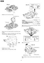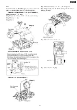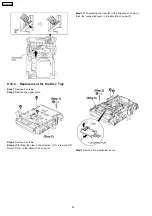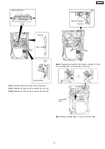
spread the hold bars of loading stopper and remove the
UP/DOWN base.
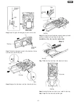
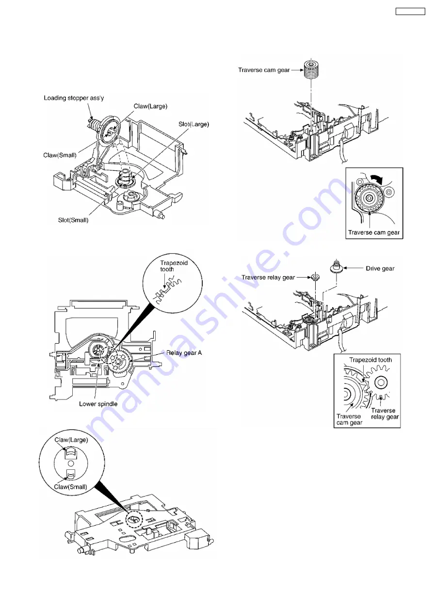
[Installation for loading stopper ass’y]
Step 1
Align the claw of loading stoppers ass’y with the slot of
spindle base. (Caution should be exercised when alignment of
claw due to the size of claws.)
Step 2
Lower the loading stopper ass’y, and then align the
lower spindle with the trapezoid tooth of relay gear A.
Step 3
Force the loading stopper ass’y, latch the claw firmly.
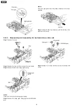
[Reassembly for mechanism base drive unit]
Step 1
Install the traverse cam gear.
Step 2
Rotate the traverse cam gear to the direction of arrow.
Step 3
Install the drive gear and traverse relay gear.
*When installing the traverse relay gear, align the trapezoid
tooth of gear with tooth of traverse cam gear.
29
SA-AK330EE
Содержание SA-AK330EE
Страница 8: ...7 Accessories Remote Control FM Antenna AC Cord AM Loop Antenna 8 SA AK330EE ...
Страница 9: ...8 Operation Procedures 9 SA AK330EE ...
Страница 10: ...10 SA AK330EE ...
Страница 57: ...15 Voltage Measurement 57 SA AK330EE ...
Страница 58: ...58 SA AK330EE ...
Страница 89: ...21 Troubleshooting Guide 89 SA AK330EE ...
Страница 91: ...22 1 Deck Mechanism RAA4502 S 22 1 1 Deck Mechanism Parts Location 91 SA AK330EE ...
Страница 92: ...92 SA AK330EE ...
Страница 94: ...22 2 CD Loading Mechanism RD DAC026 S 22 2 1 CD Loading Mechanism Parts Location 94 SA AK330EE ...
Страница 95: ...95 SA AK330EE ...
Страница 97: ...22 3 1 Cabinet Parts Location 22 3 Cabinet 97 SA AK330EE ...
Страница 98: ...98 SA AK330EE ...
Страница 108: ...22 6 Packaging 108 SA AK330EE PRT0412 P S J N A E ...


