


26
8.6.2.
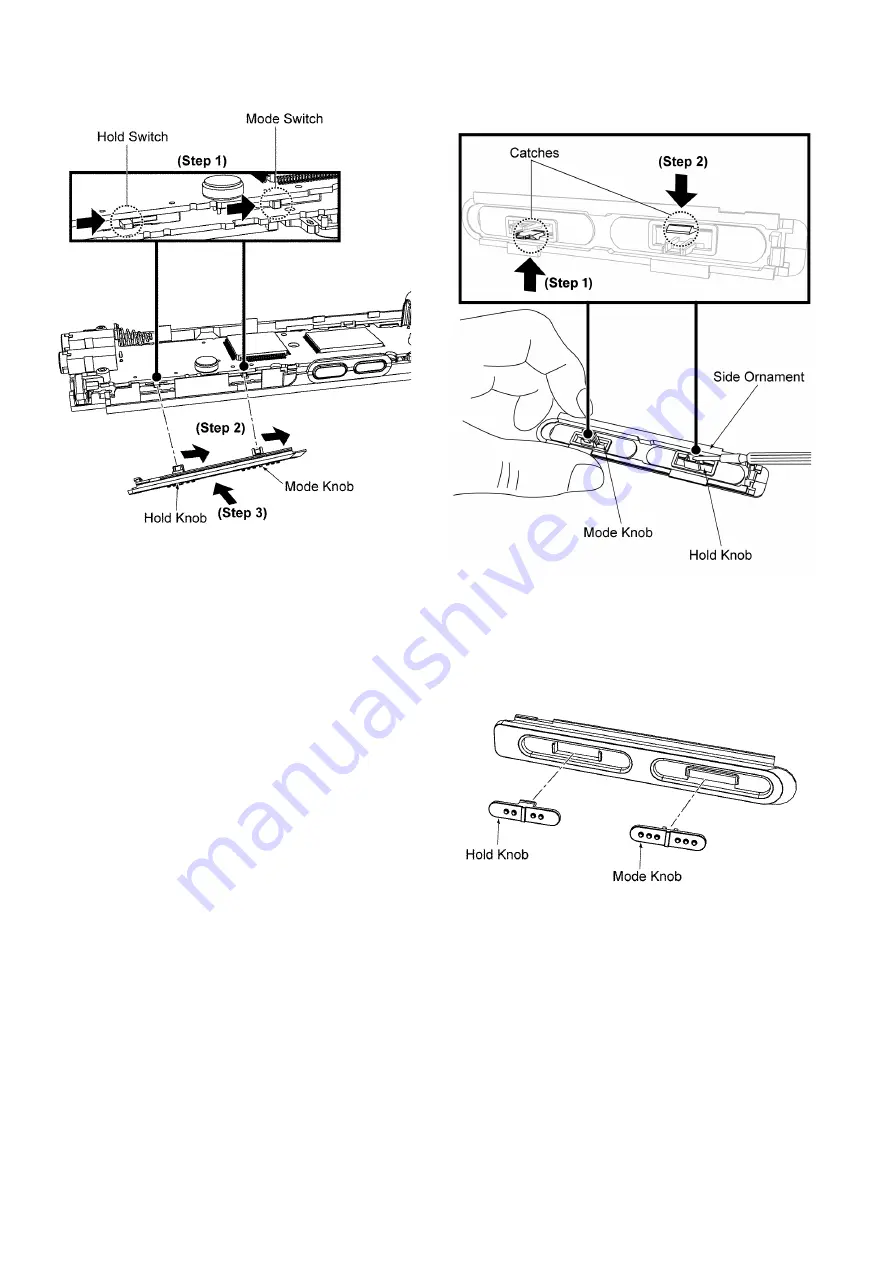
Assembly of Side Ornament
Step 1 :
Push Hold switch and Mode switch to the extreme
right.
Step 2 :
Push Hold Knob and Mode Knob to the extreme right.
Step 3 :
Slide in the Side Ornament.
Caution : Ensure Hold Switch and Mode Switch are prop-
erly seated in the Hold Knob and Mode Knob.
8.6.3.
Disassembly of Mode Knob and
Hold Knob
Step 1 :
Release the catch to remove the Mode Knob.
Step 2 :
Release the catch to remove the Hold Knob.
Caution 1 : Do not apply strong force in releasing the catch
to avoid damage of the catch.
Caution 2 : Ensure that Mode Knob and Hold Knob are
fixed at the correct location during assembly.
Содержание RR-US570PP
Страница 8: ...8 5 Location of Controls and Components 5 1 Components of IC Recorder ...
Страница 9: ...9 5 2 Basic Operation ...
Страница 14: ...14 7 Troubleshooting Guide ...
Страница 15: ...15 ...
Страница 16: ...16 ...
Страница 18: ...18 8 1 Main Parts Location Diagram ...
Страница 44: ...44 11 Illustration of IC s Transistors and Diodes C1AB00003086 120P RFKWNUS570 S RFKWNUS590 K ...