


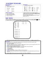


ADJUSTMENT PROCEDURE
Item / Preparation
Adjustments
+B SET-UP
1. Receive a Greyscale signal.
2. Set the controls :
Brightness
Minimum
Contrast
Minimum
Volume
Minimum
Confirm the following voltages.
B2
148
±
2V
B9
5
± 0,25V
B10
5
±
0,25V
B5
12
±
0,5V
B11
33
±
1,5V
B4
15 ± 1V
B7
8
±
0,5V
B12
26
± 1V
B8
6
±
1V
B3
36
± 1,5V
B13
15
±
1V
B1
205
± 10V
B14
-15
±
1V
CUT OFF / Ug2 Test
1. Receive a Greyscale signal.
2. Degauss the tube externally.
3. Set the TV into Service Mode 1.
4. Select Cut off mode.
To adjust Cutoff connect an oscilloscope to the Blue
cathode, adjust "cutoff" value using the "
Yellow
" and "
Blue
"
buttons until the black level is 160V±5V press "
STR
" to store
the value. Remove the oscilloscope.
Select Ug2 adjustment and adjust the screen VR until the
display shows "O.K."
SELF CHECK
Self-check is used to automatically check the bus lines and hexadecimal code of the TV set.To enter Self-Check mode. press
the down
(-/v)
button on the customer controls at the front of the TV set, at the same time pressing the
STATUS
button
on the remote control. To exit Self Check, switch off the TV set at the power button.
If the CCU ports have been checked and found to be incorrect or not located then " - - " will appear in place of "O.K.".
Service Aids
To aid in the service of our current chassis there are a number of Service Aids which have been made available.
•
LUCI
interface kit (
L
inked
U
tility
C
omputer
I
nterface)
Part number: TZS6EZ002
This contains interface and cables for connecting TV service connector and a PC as well as diagnostic software. As new
models are introduced upgrade software will become available.
•
VICI
(
V
isual
I
nteractive
C
omputer
I
nformation)
These C.D.'s contain multimedia documentation providing quick access to service information.
Part No. TZS7EZ006, TZS7EZ005, TZS8EZ001 & TZS9EZ001
1. Service Manuals
2. Instruction Books
3. Technical Information
•
TASMIN
(
T
echnically
A
dvanced
S
ystem
for
M
ultimedia
I
nteractive
N
otes)
As well as providing a first step towards more interactive training this product also achieves quick access to Technical
Information.
•
Extended cable kit Y2-E8 connector for service position (Fig.6.). Part No.: TZS9EK012.
VPC
O.K.
CIP
O.K.
SRC
O.K.
DDP
O.K.
TUN
O.K.
E2
O.K.
MSP
O.K.
DPL
- - -
PCB
O.K.
CAB
O.K.
OPTION 1
3D
OPTION 2
3E
OPTION 3
0F
OPTION 4
40
OPTION 5
FD
OPTION 6
A1
5
Содержание QuintrixF TX-29AS10P
Страница 6: ...WAVEFORM PATTERN TABLE 6 CONDITIONS CONTRAST MAX BRIGHTNESS MID COLOUR MID SHARPNESS MID ...
Страница 23: ...23 NOTES ...
Страница 25: ......
Страница 26: ......
Страница 27: ......
Страница 28: ......
Страница 29: ......
Страница 34: ...F BOARD TNP8EF007 TRAN S Q1501 C3 Q1508 C1 Q1509 C2 Q1510 C2 Q1511 C1 Q1512 D1 Q1513 C1 1 2 3 A B C D 34 ...
Страница 35: ...P BOARD TNP8EP017 DIODES D580 B2 35 A B C D 1 2 3 E ...