


be between 1 M and 12 M . When the exposed metal does not
have a return path to the chassis, the reading must be infinity.
LEAKAGE CURRENT HOT CHECK
1. Plug the AC cord directly into the AC outlet.
Do not use a isolation transformer for this check.
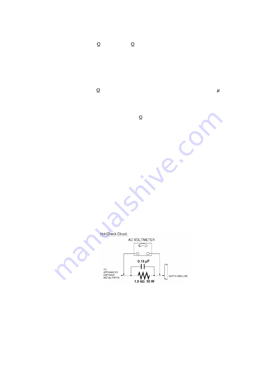
2. Connect a 1.5 k , 10 W resistor, in parallel with a 0.15 F
capacitor, between each exposed metallic part on the set and a
good earth ground , as shown in Figure 1.
3. Use an AC voltmeter, with 1 k /V or more sensitivity, to measure
the potential across the resistor.
4. Check each exposed metallic part, and measure the voltage at
each point.
5. Reverse the AC plug in the AC outlet and repeat each of the above
measurements.
6. The potential at any point should not exceed 0.75 V RMS.
A leakage current tester (Simpson Model 229 equivalent) may be
used to make the hot checks. Leakage current must not exceed 1/2
mA. In case a measurement is outside of the limits specified, there
is a possibility of shock hazard, and the receiver should be
repaired and rechecked before it is returned to the customer.
Figure 1
2. X-RADIATION
WARNING :
1. The potential source of X-Radiation in TV sets is the High Voltage
section and the picture tube.
2. When using a picture tube test fixture for service, ensure that the
fixture is capable of handling 25.0 kV (Model: A, B, C, D, E, F, G) or
4
Содержание Quasar PVQ-1310
Страница 24: ...6 S 1 6 Screws S 1 6 L 1 6 Locking Tabs L 1 P 1 Spring P 1 E Refer to Notes in chart Fig D2 Fig D3 Fig D4 24 ...
Страница 25: ...Fig D5 25 ...
Страница 29: ...6 2 2 Inner Parts Location Fig J1 1 29 ...
Страница 30: ...6 2 3 EJECT Position Confirmation Fig J1 2 30 ...
Страница 31: ...6 2 4 Grounding Plate Unit Full Erase Head and Cylinder Unit Fig J2 1 31 ...
Страница 33: ...6 2 5 Capstan Belt Support Angle Intermediate Gear B and Main Cam Gear Fig J3 1 6 2 5 1 Reassembly Notes 33 ...
Страница 44: ...6 3 CASSETTE UP ASS Y SECTION 6 3 1 Top Plate Wiper Arm Unit and Holder Unit Fig K1 1 44 ...
Страница 82: ...82 ...
Страница 86: ...11 2 MECHANISM BOTTOM SECTION 86 ...
Страница 87: ...11 3 CASSETTE UP COMPARTMENT SECTION 87 ...
Страница 88: ...11 4 CHASSIS FRAME SECTION 1 A B C D E F G 88 ...
Страница 89: ...11 5 CHASSIS FRAME SECTION 1 H I J K L 89 ...
Страница 90: ...11 6 CHASSIS FRAME SECTION 2 90 ...
Страница 91: ...11 7 PACKING PARTS AND ACCESSORIES SECTION A B C D E F G 91 ...
Страница 92: ...11 8 PACKING PARTS AND ACCESSORIES SECTION H I J K L 92 ...
Страница 113: ...R4021 ERJ6GEYJ473V MGF CHIP 1 10W 47K 113 ...
Страница 115: ...R5515 ERDS2TJ332 3 3K 115 ...
Страница 135: ...R885 ERDS2TJ104 100K 135 ...


