releasing the mouse or key after pressing it continuously,
the data is transmitted once. The variable setting value is
enclosed ina box and using the TAB or SPACE key allows
the move of the box.
OK:
Determines the setting value and stores its data in the
EEPROM. (The ENTER key on the keyboard has the same
function.) The item having two or more kinds of setting
values is processed two or more items. Clicking this button
or pressing ENTER keychanges the color of the text "OK" to
cyan (light blue). If changing the setting value using the "
" or "
" button or the 8or 2 key, its color returns to
black.
Stop:
Discontinues the communication. (This button is usually set
for its inactive mode.)
Undo:
Returns the setting value to its original state and transmits
its data. The color of the text "OK" returns to black.
Close:
Closes this menu.
9.8.2. Explanation of Buttons
OK:
Executes automatic sub contrast and sub brightness
adjustments, then closes this dialog.
Cancel:
Cancels this menu.
9.8.3. Equipment to be used
PC, RGB Signal Generator, Software for Adjustment
9.8.4. Adjustment Procedure
1. Display the input level adjustment (RGB) menu.
2. Input a window pattern signal to RGB1 IN connector.
Note:
·
Use approx. 15 % window pattern as follows.
Black background (screen width) : White window
width = 2 : 1
Black background (screen height) : White window
height = 3 : 1
·
Use the window pattern of XGA (1 024×768).
3. Click the OK button.
9.7.3. Equipment to be used
PC, Software for Adjustment
9.7.4. Adjustment Procedure
1. Display the flicker adjustment menu.
2. Set the installation mode to the desk setting.
3. Click "B Signal Adj." and the blue flicker adjustment pattern
will be displayed.
4. Minimize the flicker while observing the projected pattern.
5. Click "R Signal Adj." and the red flicker adjustment pattern
will be displayed.
6. Minimize the flicker while observing the projected pattern.
7. Click "G Signal Adj." and the green flicker adjustment
pattern will be displayed.
8. Minimize the flicker while observing the projected pattern.
9. Change the installation mode to the ceiling setting and
follow steps 3 to 8 inclusive.
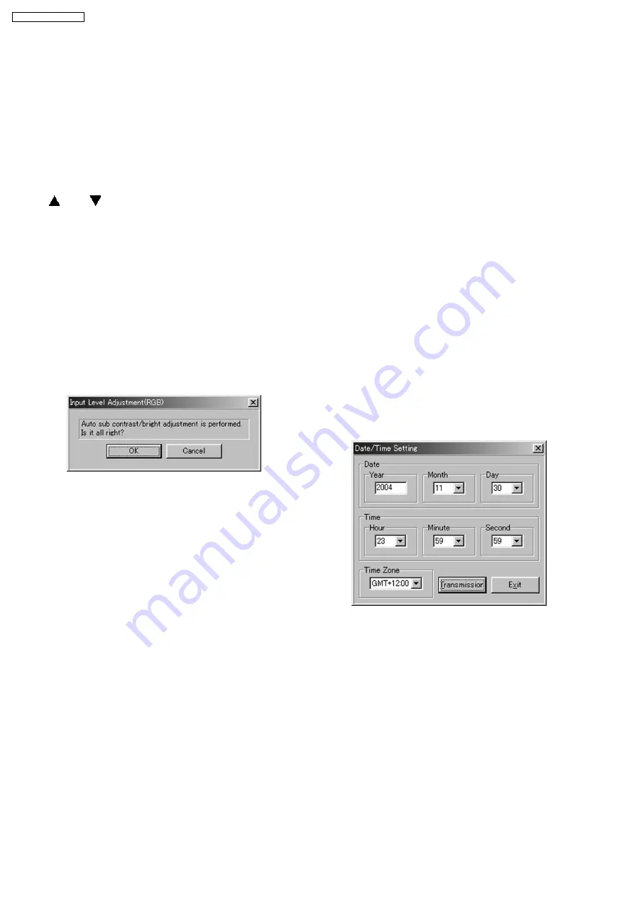
9.9. Date / Time Setting
9.9.1. Setting Menu
9.9.2. Explanation of Buttons
Transmission:
Transmits the date/time setting values to the projector.
Exit:
Exits this application.
9.9.3. Setting Procedure
1. Display the date/time setting menu.
2. Confirm or correct (by the keyboard entry) the Year.
3. Confirm
or
correct
(with
the
select
box)
the
Month/Day/Hour/Minute/Second.
4. Select the Time Zone with the select box.
5. Click the Transmission button.
9.8. RGB Input Level Adjustment
9.8.1. Adjustment Menu
28
PT-L785U / PT-L785E
Содержание PTL785U - LCD PROJECTOR UNIT
Страница 2: ...2 PT L785U PT L785E...
Страница 3: ...1 Safety Precautions 5 1 1 General Guidelines 5 CONTENTS Page Page 3 PT L785U PT L785E...
Страница 11: ...Query Commands 11 PT L785U PT L785E...
Страница 29: ...10 Troubleshooting 29 PT L785U PT L785E...
Страница 30: ...30 PT L785U PT L785E...
Страница 31: ...31 PT L785U PT L785E...
Страница 32: ...32 PT L785U PT L785E...
Страница 33: ...33 PT L785U PT L785E...
Страница 34: ...34 PT L785U PT L785E...
Страница 35: ...35 PT L785U PT L785E...
Страница 36: ...36 PT L785U PT L785E...
Страница 37: ...37 PT L785U PT L785E...
Страница 38: ...38 PT L785U PT L785E...
Страница 39: ...39 PT L785U PT L785E...
Страница 40: ...40 PT L785U PT L785E...
Страница 41: ...41 PT L785U PT L785E...
Страница 42: ...42 PT L785U PT L785E...
Страница 44: ...11 2 Interconnection Block Diagram 2 2 Interconnection Block Diagram 2 2 A P C Board PT L785U PT L785E 44...
Страница 49: ...13 Schematic Diagram PT L785U PT L785E 49...
Страница 50: ...13 1 A P C Board 1 8 A P C Board TXANP04VJX7 1 8 PT L785U PT L785E 50...
Страница 51: ...13 2 A P C Board 2 8 TXANP04VJX7 2 8 A P C Board PT L785U PT L785E 51...
Страница 52: ...13 3 A P C Board 3 8 A P C Board TXANP04VJX7 3 8 PT L785U PT L785E 52...
Страница 53: ...13 4 A P C Board 4 8 A P C Board TXANP04VJX7 4 8 PT L785U PT L785E 53...
Страница 54: ...13 5 A P C Board 5 8 TXANP04VJX7 5 8 A P C Board PT L785U PT L785E 54...
Страница 55: ...13 6 A P C Board 6 8 A P C Board TXANP04VJX7 6 8 PT L785U PT L785E 55...
Страница 56: ...13 7 A P C Board 7 8 TXANP04VJX7 7 8 A P C Board PT L785U PT L785E 56...
Страница 57: ...13 8 A P C Board 8 8 TXANP04VJX7 8 8 A P C Board PT L785U PT L785E 57...
Страница 60: ...13 11 J P C Board S P C Board J P C BOARD TNPA2624 S P C BOARD TNPA2546 PT L785U PT L785E 60...
Страница 64: ...PT L785U PT L785E 64...
Страница 65: ...15 Terminal guide of ICs and transistors PT L785U PT L785E 65...
Страница 66: ...16 Exploded Views PT L785U PT L785E 66...
Страница 67: ...PT L785U PT L785E 67...
Страница 68: ...PT L785U PT L785E 68...
Страница 69: ...PT L785U PT L785E 69...


