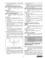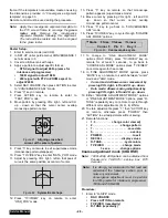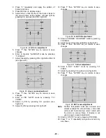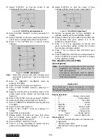
- 41 -
Service Manual
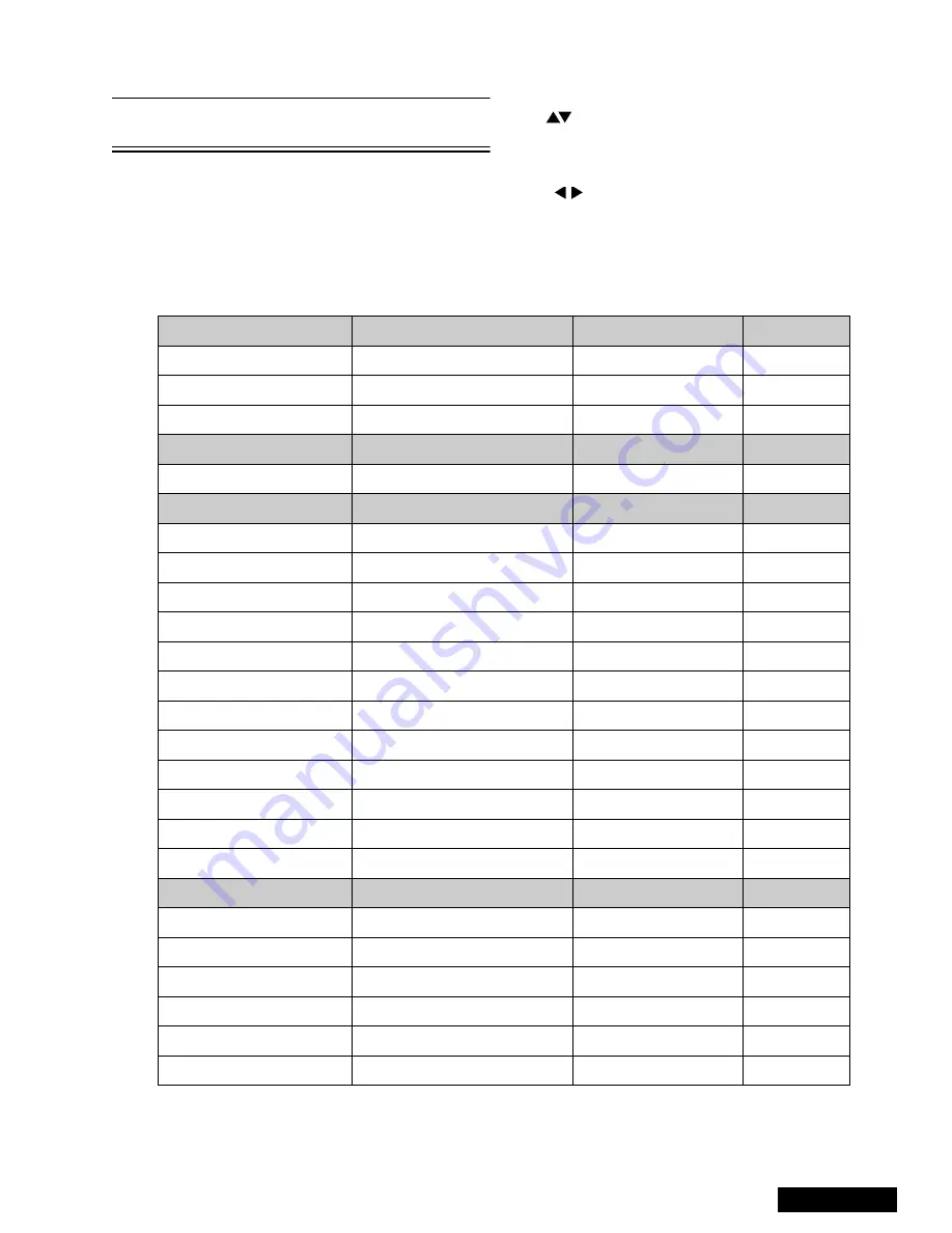
1080i Service mode (electronic controls, continued)
Note:
Registers marked as FIXED are factory preset,
the default value must not be changed
Important note:
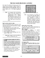
Write down the original values (“b” in the
adjustment mode details, figure 60) for each
address adjustment before modifying values.
Follow the procedure below to access the various
service adjustments. (Same procedures applies to
each section.)
a.
Press
CH
buttons on the remote control to select any of
the seven service sub adjustment addresses. (“a” in
figure 60)
b. Press
The
buttons on the remote control to adjust the
level of the selected service adjustments.
MTS Adjustments
Description
Default Level
New Level
MTSIN
INPUT LEVEL
N/A
SEPAL
LOW LEVEL SEPARATION
N/A
SEPAH
HIGH LEVEL SEPARATION
N/A
CLOCK Adjustments
Description
Default Level
New Level
CLOCK
CLOCK
N/A
VIDEO Adjustments
Description
Default Level
New Level
COLOR
COLOR
1C
TINT
TINT
80
BRIGHT
SUB-BRIGHTNESS
02 00
CONT
SUB-CONTRAST
89
B-Y_G
MAGENTA TINT ADJ
40
R-Y_A
YELLOW TINT ADJ
80
CUT R
RED CUT-OFF
01 FB
CUT B
BLUE CUT-OFF
01 EC
R DR
RED DRIVE
57
B DR
BLUE DRIVE
70
I ABL
ABL
00
C_OFF
COLOR ADJ. CUT-OFF
00
HDEF Adjustments
Description
Default Level
New Level
H POS
HORIZONTAL POSITIONING
00 C2
H WID
HORIZONTAL WIDTH
2B
PCC
PINCUSHION CORRECTION
0C
EWCOR
CORNER CORRECTION
03
EWTRA
TRAPEZOID
08
HCORR
HORIZONTAL CORRECTION
0E
Содержание PT47WX52F - 47" PROJECTION TV HD
Страница 65: ... 65 Notes PARTS LIST ...
Страница 66: ... 66 D Board Schematic ...
Страница 67: ... 67 D Board Schematic ...
Страница 68: ... 68 D Board Schematic ...
Страница 69: ... 69 Jumper between pin 7 and pin 1 D Board Schematic ...
Страница 70: ... 70 D Board Schematic ...
Страница 71: ... 71 D Board Schematic ...
Страница 73: ... 73 NOTES NOTES ...
Страница 74: ... 74 D Board Layout ...
Страница 75: ... 75 D Board Layout ...
Страница 76: ... 76 A Board Schematic ...
Страница 77: ... 77 A Board Schematic ...
Страница 78: ... 78 A Board Schematic ...
Страница 79: ... 79 A Board Schematic ...
Страница 80: ... 80 A Board Schematic ...
Страница 81: ... 81 A Board Schematic ...
Страница 82: ... 82 A Board Schematic ...
Страница 83: ... 83 A Board Schematic ...
Страница 84: ... 84 Board section Top A Board Layout Top left portion ...
Страница 85: ... 85 Board section Top A Board Layout Top right portion ...
Страница 86: ... 86 Board section Top A Board Layout Bottom left portion ...
Страница 87: ... 87 Board section Top A Board Layout Bottom right portion ...
Страница 88: ... 88 Board section Bottom side A Board Layout Top left portion ...
Страница 89: ... 89 Board section Bottom A Board Layout Top right portion ...
Страница 90: ... 90 Board section Bottom A Board Layout Bottom left portion ...
Страница 91: ... 91 Board section Bottom A Board Layout Bottom right portion ...
Страница 92: ... 92 LG Board schematic TNP2AA112 LG Board schematic ...
Страница 94: ... 94 LR Board schematic TNP2AA111 LR Board schematic ...
Страница 96: ... 96 LB Board schematic TNP2AA110 LB Board schematic ...
Страница 98: ... 98 K Board schematic TNP2AA089 K Board layout TNP2AA089 K Board schematic and layout ...
Страница 99: ... 99 G Board schematic TNP2AA090 G Board layout TNP2AA090 G Board schematic and layout ...
Страница 104: ...Printed in USA K02042127PL0429 ...

