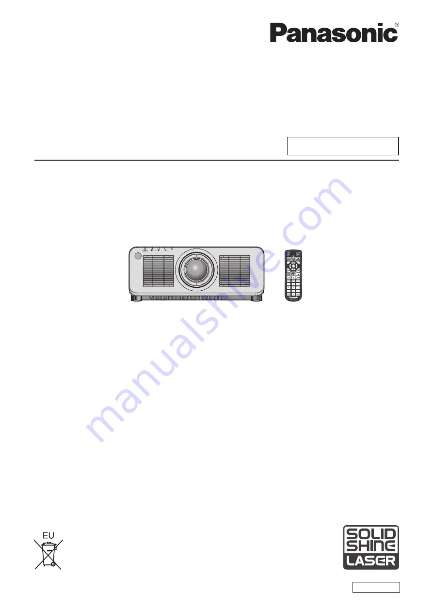
Panasonic PT-RCQ80 Скачать руководство пользователя страница 1

Thank you for purchasing this Panasonic product.


This manual is common to all the models regardless of suffixes of the Model No.


z

for USA, Canada, EU countries

B: Black model, the standard zoom lens supplied 

LB: Black model, the lens sold separately

W: White model, the standard zoom lens supplied 

LW: White model, the lens sold separately


z

for Korea

B: Black model, the standard zoom lens supplied 

W: White model, the standard zoom lens supplied


z

for India

BD: Black model, the standard zoom lens supplied   

LBD: Black model, the lens sold separately


z

for Taiwan

B: Black model, the standard zoom lens supplied  


z

for other countries or regions with power cord for 100 V - 120 V

BX: Black model, the standard zoom lens supplied   

LBX: Black model, the lens sold separately

WX: White model, the standard zoom lens supplied   

LWX: White model, the lens sold separately


z

for other countries or regions with power cord for 200 V - 240 V

BE: Black model, the standard zoom lens supplied   

LBE: Black model, the lens sold separately

WE: White model, the standard zoom lens supplied   

LWE: White model, the lens sold separately


Before operating this product, please read the instructions carefully and save this manual 

for future use.


Before using this product, be sure to read “Read this first!” (

x

 pages 5 to 16).

DPQP1295ZA/X1

DLP™ Projector  

Commercial Use

Operating Instructions

Functional Manual

ENGLISH

Model No. 

PT-RCQ10


PT-RCQ80

Содержание PT-RCQ80

Страница 1: ...upplied z z for other countries or regions with power cord for 100 V 120 V BX Black model the standard zoom lens supplied LBX Black model the lens sold separately WX White model the standard zoom lens...

Страница 2: ...4 Before connecting 54 Connecting example AV equipment 55 Connecting example Computers 58 Connecting example using DIGITAL LINK 59 Connecting example when using the contrast synchronization function s...

Страница 3: ...FF 140 PROJECTOR SETUP menu 141 PROJECTOR ID 141 PROJECTION METHOD 141 LENS 142 OPERATION SETTING 143 LIGHT OUTPUT 146 BRIGHTNESS CONTROL 147 STANDBY MODE 151 QUICK STARTUP 151 NO SIGNAL SETTING 152 I...

Страница 4: ...ght source temperature indicators 222 When an indicator lights up 222 Maintenance 224 Before maintaining the projector 224 Maintenance 224 Troubleshooting 225 SELF TEST indications 227 Chapter 7 Appen...

Страница 5: ...n earthing type mains socket This is a safety feature If you are unable to insert the plug into the mains socket contact an electrician Do not defeat the purpose of the earthing plug WARNING This equi...

Страница 6: ...light emitted from the lens while the projector is being used As with any bright source do not stare into the direct beam RG2 IEC 62471 5 2015 Indicated on the projector Notice on laser for USA and Ca...

Страница 7: ...ols or adjustments or performance of procedures other than those specified herein may result in hazardous radiation exposure CAUTION North Middle South America Power Supply This Projector is designed...

Страница 8: ...sponsible Party Panasonic Corporation of North America Address Two Riverfront Plaza Newark NJ 07102 5490 General Contact http www panasonic com support Projector Contact https panasonic net cns projec...

Страница 9: ...13 amp socket If a new plug is to be fitted please observe the wiring code as shown below If in any doubt please consult a qualified electrician WARNING THIS APPLIANCE MUST BE EARTHED IMPORTANT The wi...

Страница 10: ...ction lens which the hazard distance exceeds 1 m 39 3 8 and is categorized as risk group 3 is as follows Projection lens Model No Risk group ET DLE250 Risk group 3 1 ET DLE350 ET DLE450 1 When the pro...

Страница 11: ...D3 2 D4 2 PT RCQ10 ET DLE250 1 4 0 40 0 27 0 52 0 39 ET DLE350 2 2 0 40 0 27 0 52 0 39 ET DLE450 3 2 0 40 0 27 0 51 0 38 PT RCQ80 ET DLE250 1 2 0 37 0 23 0 45 0 34 ET DLE350 1 9 0 37 0 23 0 45 0 34 E...

Страница 12: ...ector with wet hands Failure to observe this will result in electric shocks Use an outlet supporting 15 A independently Using an outlet together with another device may result in fires due to heat gen...

Страница 13: ...eiling should only be carried out by a qualified technician If installation is not carried out and secured correctly it can cause injury or accidents such as electric shocks r r ACCESSORIES Do not use...

Страница 14: ...projector Do not place the projector in extremely hot locations Doing so will cause the outer casing or internal components to deteriorate or result in fire f f Take particular care in locations expos...

Страница 15: ...fire or explode which may result in fire or contamination of surrounding area r r MAINTENANCE Ask your dealer about cleaning inside the projector every 20 000 hours of usage as an estimated duration...

Страница 16: ...do pela bateria pode irritar a garganta danificar o lacre do inv lucro ou o vazamento provocar calor ruptura da blindagem e produzir fogo devido ao curto circuito dos terminais N o incinere nem aque a...

Страница 17: ...ymbols are not specified in this manual Software information regarding this product This product incorporates the following software 1 the software developed independently by or for Panasonic Corporat...

Страница 18: ...nting the Interface Board providing the flexibility to support various signal input structures Long life and high reliability In addition to adopting the solid state light source with long life the pr...

Страница 19: ...ENGLISH 19 Chapter 1 Preparation This chapter describes things you need to know or check before using the projector...

Страница 20: ...f f Do not transport the projector with the adjustable feet extended Doing so may damage the adjustable feet Cautions when installing r rAfter attaching the projection lens be sure to attach the Lens...

Страница 21: ...l foil or a metal pipe which is grounded at both ends r rFocus adjustment The high clarity projection lens is thermally affected by the light from the light source making the focus unstable in the per...

Страница 22: ...than the floor installation using the adjustable feet top placed on the floor or the ceiling installation with the Ceiling Mount Bracket use the five screw holes for ceiling mount as shown in the figu...

Страница 23: ...arty Take sufficient security measures f f Make your password difficult to guess as much as possible f f Change your password periodically A password can be set in the SECURITY menu SECURITY PASSWORD...

Страница 24: ...AJ WM50 Series r rDo not use close to other wireless devices Following devices may be using radio wave in the same bandwidth as the projector Using the projector close to these devices may cause the...

Страница 25: ...anel display connected to an intranet f f Early Warning Software This plug in software monitors the status of the display devices and their peripherals within an intranet and notifies of abnormality o...

Страница 26: ...amage the DLP chips r rDo not move the projector or subject it to vibration or impact while it is operating Doing so may shorten the life of the built in motor r rLight source The light source of the...

Страница 27: ...del 1GE1RZ970WU The same color as the outer case will be supplied Lens cover 1 TKKL5244 1 Only models with lens AAA R03 or AAA LR03 battery 2 For remote control unit Attention f f After unpacking the...

Страница 28: ...depending on the country For details contact your dealer 3 The suffix of the Model No differs depending on the country Example of the Model No with suffix for AJ WM50 Series AJ WM50E AJ WM50G1 AJ WM5...

Страница 29: ...the slot 9 FUNCTION button Assigns a frequently used operation as a shortcut button x page 84 When the FUNCTION button is held down the FUNCTION BUTTON screen is displayed x page 162 10 Number 0 9 but...

Страница 30: ...control can control at angles of up to 30 vertically and horizontally but the effective control range may be reduced f f If there are any obstacles between the remote control and the remote control si...

Страница 31: ...source indicator LIGHT2 Indicates the status of light source 2 5 Temperature indicator TEMP Indicates the internal temperature status 6 Not used with this projector 7 Adjustable feet Adjusts the proje...

Страница 32: ...cns projector r r Control panel 5 6 7 8 9 10 2 4 3 1 1 Power on b button Sets the projector to projection mode when the MAIN POWER switch on the projector is set to ON and the power is turned off sta...

Страница 33: ...ower supply DC 5 V 500 mA 7 REMOTE 1 IN terminal REMOTE 1 OUT terminal These are terminals to connect the remote control for serial control in a multiple projector environment 8 REMOTE 2 IN terminal T...

Страница 34: ...del No ET MDN12G10 This board supports the HD SDI signal 3G SDI signal 6G SDI signal and 12G SDI signal 2 5 5 4 1 3 1 SDI 1 IN terminal This is a terminal to input SDI signal HD SDI 3G SDI 6G SDI 12G...

Страница 35: ...ace Board for DisplayPort 2 input Model No ET MDNDP10 This board supports the DisplayPort signal 1 3 3 2 1 DisplayPort IN 1 terminal This is a terminal to input DisplayPort signal 2 DisplayPort IN 2 t...

Страница 36: ...o ALL so you can use it as it is Set the ID numbers of the projector body and remote control as necessary For details on setting the ID number of the remote control refer to Setting ID number of the r...

Страница 37: ...ENGLISH 37 Chapter 2 Getting Started This chapter describes things you need to do before using the projector such as the setup and connections...

Страница 38: ...the outlet f f Use the power cord matching the used power supply voltage and outlet shape Note f f The supplied power cords vary depending on the country or region where you purchased the product Inst...

Страница 39: ...accordance with the image to project FLOOR CEILING Set in accordance with the image to project Note f f In the portrait setting the on screen menu is displayed sideways To display the on screen menu...

Страница 40: ...mage size and projection distance Image size and image position can be adjusted in accordance with the screen size and screen position The projection relation between the screen and the projector diff...

Страница 41: ...d image position with the lens shift refer to Lens shift range x page 80 r r Fixed focus Lens Model No ET DLE035 SH SW SD SH A1 L3 L4 A2 L1 L2 SW Projected image Screen Screen Note f f This illustrati...

Страница 42: ...hen installing the projector in a confined space provide air conditioning or ventilation separately Exhaust heat may accumulate when the ventilation is not enough triggering the protection circuit of...

Страница 43: ...ED CORRECTION used Vertical keystone correction angle Horizontal keystone correction angle Vertical keystone correction angle Horizontal keystone correction angle Min value of R2 L2 Min value of R3 L3...

Страница 44: ...1 10 770 18 86 26 36 6 75 8 90 8 67 10 75 10 80 14 50 15 24 600 8 077 12 923 22 64 31 65 8 11 10 69 10 42 12 91 12 97 17 41 1 The throw ratio is based on the value during projection of 2 03 m 80 proje...

Страница 45: ...ection distance L Height position H 3 Projection distance L1 Distance from the projector to the screen Diagonal SD Height SH Width SW L4 A1 1 27 50 0 673 1 077 0 83 0 34 1 52 60 0 808 1 292 1 00 0 40...

Страница 46: ...0 99 10 71 13 27 13 33 17 90 1 The throw ratio is based on the value during projection of 2 03 m 80 projected image size When the Zoom Lens Model No ET DLE020 is attached the throw ratio is based on t...

Страница 47: ...ojected image size Projection distance L Height position H 3 Projection distance L1 Distance from the projector to the screen Diagonal SD Height SH Width SW L4 A1 1 27 50 0 623 1 107 0 85 0 31 1 52 60...

Страница 48: ...1 11 80 14 62 14 69 19 72 1 The throw ratio is based on the value during projection of 2 03 m 80 projected image size When the Zoom Lens Model No ET DLE020 is attached the throw ratio is based on the...

Страница 49: ...ection distance L Height position H 3 Projection distance L1 Distance from the projector to the screen Diagonal SD Height SH Width SW L4 A1 1 27 50 0 762 1 016 0 94 0 38 1 52 60 0 914 1 219 1 14 0 46...

Страница 50: ...9 0 7056 x SD 0 0471 0 8735 x SD 0 0442 0 943 1 18 1 4 3 0 7772 x SD 0 0471 0 9621 x SD 0 0442 ET DLE105 0 978 1 32 1 16 10 0 8543 x SD 0 0511 1 1457 x SD 0 0472 0 979 1 32 1 16 9 0 8781 x SD 0 0511...

Страница 51: ...becomes rectangular The adjustable feet can also be used to adjust the projector to be level when it is tilted in the horizontal direction Adjustable feet can be extended by turning them as shown in t...

Страница 52: ...removal procedures of the Lens Mount Cover are different Refer to the Operating Instructions of ET DLE020 ET DLE060 ET DLE085 or ET DLE105 for details f f In case of the Fixed focus Lens Model No ET...

Страница 53: ...Fig 1 2 Turn the projection lens clockwise until it clicks Fig 2 3 Attach the Lens Mount Cover Fig 3 f f Align the Lens Mount Cover and the projector at the dashed line positions in the figure to att...

Страница 54: ...r to the slot in advance Requesting a qualified technician to install or remove the optional Interface Board is recommended A malfunction may occur due to static electricity Consult your dealer For de...

Страница 55: ...DVI D IN terminal can be connected with the HDMI and DVI D compatible devices However some external devices may not be able to project images properly such as the image not displaying f f For the HDM...

Страница 56: ...High Speed cable that conforms to the HDMI standards However when the following 4K video signal exceeding the supported transmission speed of the HDMI High Speed cable is to be input use the HDMI cab...

Страница 57: ...sed the cable length should be 90 m 295 3 f f When the DISPLAY OPTION menu SLOT IN SDI MODE is set to OUTPUT attach a terminating resistor 75 to the terminal with no device connected as an output dest...

Страница 58: ...hen DVI D signal is input f f Switching of the setting in the DISPLAY OPTION menu HDMI IN EDID SELECT may be required depending on the connected external device when HDMI signal is input f f For the H...

Страница 59: ...laying cables between the twisted pair cable transmitter and the projector confirm that cable characteristics are compatible with CAT5e or higher using tools such as a cable tester or cable analyzer...

Страница 60: ...manufacturers of which the operation has been verified with the projector visit the Panasonic website https panasonic net cns projector Note that the verification for devices of other manufacturers ha...

Страница 61: ...chronization function and the shutter synchronization function refer to the PROJECTOR SETUP menu MULTI PROJECTOR SYNC x page 159 f f The menu items in the PROJECTOR SETUP menu MULTI PROJECTOR SYNC are...

Страница 62: ...hronization function refer to the PROJECTOR SETUP menu MULTI PROJECTOR SYNC x page 159 f f The menu items in the PROJECTOR SETUP menu MULTI PROJECTOR SYNC are common with the following setting items g...

Страница 63: ...ENGLISH 63 Chapter 3 Basic Operations This chapter describes basic operations to start with...

Страница 64: ...38 Note f f The supplied power cords vary depending on the country or region where you purchased the product How to attach the power cord Fig 3 Fig 4 Fig 2 Fig 1 Power cord holder 1 Confirm that the p...

Страница 65: ...minal of the projector while pressing the lock button Fig 2 For other countries or regions when using the power cord without the lock button Fig 1 Fig 2 1 Confirm that the MAIN POWER switch on the sid...

Страница 66: ...R lights in orange the fan is running to cool the projector f f For approximately five seconds after the projector is turned off the indicator does not light up even if the power is turned on Turn on...

Страница 67: ...ving sound This is not a malfunction f f If the power was turned off at the previous use by pressing the OFF side of the MAIN POWER switch or by using the breaker directly while projecting the power i...

Страница 68: ...UP menu OPERATION SETTING 1 Press as to select OPERATING MODE 2 Press qw to switch the item f f The items will switch each time you press the button NORMAL Set this item to prioritize the brightness T...

Страница 69: ...0 0 80 0 100 0 26 800 30 200 33 600 23 400 37 000 10 000 5 000 r r PT RCQ80 LIGHT OUTPUT Brightness lm Estimated runtime 1 hours 100 0 8 000 20 000 78 2 6 200 27 000 58 5 4 600 34 000 50 0 4 000 37 00...

Страница 70: ...D INITIAL SETTING FRONT REAR FLOOR CEILING MENU SELECT FRONT AUTO 2 Press the ENTER button to proceed to the initial setting Initial setting standby mode Set the operation mode during standby The fact...

Страница 71: ...tting f f The setting will change each time you press the button 16 10 5 7 SCREEN POSITION Set as necessary for the screen in use INITIAL SETTING SET CHANGE MENU SELECT SCREEN FORMAT ENTER 2 Press as...

Страница 72: ...f f In the factory default setting the time zone of the projector is set to 09 00 Japan and Korea Standard Time Change the setting of the PROJECTOR SETUP menu DATE AND TIME TIME ZONE to the time zone...

Страница 73: ...r attaching the projection lens x page 79 4 Press the input selection button HDMI DVI D SDI DIGITAL LINK SLOT to select the input 5 Adjust the front back and sideway tilt of the projector with the adj...

Страница 74: ...f f For approximately five seconds after the projector is turned off the indicator does not light up even if the power is turned on f f Even when the power standby v button is pressed and the projecto...

Страница 75: ...Interface Board installed in the slot The input is switched every time the button is pressed when one of the inputs is selected on the installed optional Interface Board Attention f f Images may not...

Страница 76: ...me the INPUT MENU button is pressed Note f f Input can be switched by pressing as to select the input of the image for projection and pressing the ENTER button while the input selection screen is disp...

Страница 77: ...displayed but it will not operate when a projection lens with no zoom function is attached f f When the Fixed focus Lens Model No ET DLE055 is used do not adjust the lens shift and use the projector...

Страница 78: ...justment ring 3 Check the focus at the center of the image again and make fine adjustments Note f f The projected image size and scale shown on the periphery focus adjustment ring are an approximate g...

Страница 79: ...DLE035 is used for projection ET DLE020 Select this item when the Zoom Lens Model No ET DLE020 is used for projection Moving the projection lens to the home position Operate in following procedure to...

Страница 80: ...or the SHIFT button on the remote control for at least three seconds Lens shift range The projector can adjust the position of the projected image within the lens shift range for each projection lens...

Страница 81: ...mounter Note f f Use the projection lens in the standard projection position without adjusting the lens shift when the optional Fixed focus Lens Model No ET DLE055 is attached f f When the optional Fi...

Страница 82: ...ith the projector This projector supports the commercially available USB 2 0 compatible USB memory formatted in FAT16 or FAT32 f f Only the single partition structure is supported Attaching the USB me...

Страница 83: ...closed f f The fade in fade out time of the image can be set by the DISPLAY OPTION menu SHUTTER SETTING f f The light source may be lit dimly due to warm up when the shutter function is used in the op...

Страница 84: ...tomatic adjustment may not be possible depending on the computer model f f Image may be disrupted for a few seconds during execution of the automatic setup but it is not a malfunction f f Adjustment i...

Страница 85: ...mote control for at least three seconds to set the ID number of the remote control to ALL In addition when the ID number of the projector is unknown setting the ID number to ALL enables the remote con...

Страница 86: ...86 ENGLISH Chapter 4 Settings This chapter describes the settings and adjustments you can make using the on screen menu...

Страница 87: ...NCED MENU DISPLAY LANGUAGE DISPLAY OPTION PROJECTOR SETUP TEST PATTERN SIGNAL LIST SECURITY NETWORK MENU SELECT SUB MENU ENTER 2 Press as to select an item from the main menu f f The selected item is...

Страница 88: ...low cursor by the factory default f f In the portrait setting the on screen menu is displayed sideways To display the on screen menu vertically change the setting of the DISPLAY OPTION menu ON SCREEN...

Страница 89: ...MPLE PICTURE Sub menu item Factory default SIMPLE mode Page PICTURE MODE GRAPHIC 1 l 92 CONTRAST 0 l 92 BRIGHTNESS 0 l 92 COLOR 0 2 l 93 TINT 0 93 COLOR TEMPERATURE DEFAULT 2 93 WHITE GAIN 10 95 GAMMA...

Страница 90: ...DI IN 122 DIGITAL LINK IN 124 SLOT IN 125 ON SCREEN DISPLAY l 133 MENU MODE NORMAL l 135 BACK COLOR BLUE 135 STARTUP LOGO DEFAULT LOGO l 136 UNIFORMITY 136 SHUTTER SETTING 137 FREEZE 139 WAVEFORM MONI...

Страница 91: ...Page DIGITAL LINK MODE AUTO 176 DIGITAL LINK STATUS l 176 WIRED LAN l 177 WIRELESS LAN ENABLE 1 l 177 PROJECTOR NAME l 178 NETWORK CONTROL l 178 NETWORK STATUS l 179 DIGITAL LINK MENU 180 Art Net SETU...

Страница 92: ...ation in Medicine and is a standard for medical imaging devices Although the DICOM name is used the projector is not a medical device and display images should not be used for medical purposes such as...

Страница 93: ...e of adjustment Press w Adjusts skin tone toward greenish color 31 31 Press q Adjusts skin tone toward reddish purple COLOR TEMPERATURE You can switch the color temperature if the white areas of the p...

Страница 94: ...blue Note f f Adjust COLOR TEMPERATURE correctly All colors will not be displayed properly unless adequate adjustment is made If the adjustment does not look suitable you can press the DEFAULT button...

Страница 95: ...displayed 7 Press asqw to select the text and press the ENTER button to enter the text 8 Press asqw to select OK and press the ENTER button f f The name set to color temperature is changed Note f f T...

Страница 96: ...it is projected under a bright light 1 Press as to select SYSTEM DAYLIGHT VIEW 2 Press qw or the ENTER button f f The SYSTEM DAYLIGHT VIEW individual adjustment screen is displayed 3 Press qw to switc...

Страница 97: ...justment screen is displayed 3 Press qw to switch the item f f The items will switch each time you press the button OFF Disables the dynamic contrast function 1 Adjusts the light source and compensate...

Страница 98: ...L INTENSITY Manual light source adjustment 0 255 The larger the value the stronger the correction Can be set in increments of 1 Factory setting 255 DYNAMIC GAMMA Adjustment of signal compensation OFF...

Страница 99: ...e Board equipped with the DisplayPort input is installed in the slot f f For the SDI input the signal format can be set in detail in the DISPLAY OPTION menu SDI IN DEFAULT PICTURE MODE Set the picture...

Страница 100: ...The GAMMA individual adjustment screen is displayed 7 Press qw to select 2 2 8 Press as to select COLOR 9 Press the DEFAULT button on the remote control to set the factory default setting 10 Follow St...

Страница 101: ...ertical up and down adjustment Press a The image position moves up Press s The image position moves down Horizontal right and left adjustment Press w The image position moves to the right Press q The...

Страница 102: ...e input signals is selected the images will appear differently from the originals Be careful of this when selecting the aspect ratio f f If using the projector in places such as cafes or hotels to dis...

Страница 103: ...four corners of the projected image CURVED CORRECTION Adjusts any curved distortion in the projected image PC 1 Select this item when performing correction using a computer and Geometric Setup Manage...

Страница 104: ...es to be corrected For details of operation refer to Adjusting distortion with FREE GRID x page 105 CURVED CORRECTION LENS THROW RATIO Set the throw ratio Select the value close to the actual projecti...

Страница 105: ...d For details of operation refer to Adjusting distortion with FREE GRID x page 105 Adjusting to desired linearity 1 Press as to select GEOMETRY 2 Press qw to select CORNER CORRECTION 3 Press the ENTER...

Страница 106: ...vertical direction 9 Press as to select CONTROL POINTS 10 Press qw to switch the item f f The items will switch each time you press the button POINT Select this item when adjusting by selecting one in...

Страница 107: ...TONE CORNER CORRECTION CURVED CORRECTION PC 1 PC 2 and PC 3 f f Even if GRID RESOLUTION or CONTROL POINTS is reselected the correction data adjusted before the reselection is maintained f f By selecti...

Страница 108: ...e all the correction data select each item and execute INITIALIZE individually f f When the projector is initialized by one of the following methods all data in FREE GRID are initialized g g When init...

Страница 109: ...than the 2 2 pulldown is set as 25p FIXED or 30p FIXED Vertical resolution will degrade f f When the ADVANCED MENU menu FRAME RESPONSE is set to FAST DIGITAL CINEMA REALITY cannot be set BLANKING Adj...

Страница 110: ...r at least 30 minutes and then the image is stable 1 Press as to select EDGE BLENDING 2 Press qw to switch the item f f The items will switch each time you press the button OFF Sets the edge blending...

Страница 111: ...if INTERLOCKED is set to OFF 14 Press as to select an item and press qw to adjust the setting f f Once the adjustment is completed press the MENU button to return to the BRIGHTNESS ADJUST screen 15 Pr...

Страница 112: ...rtical edge blending is used set all items in OVERLAPPED BLACK LEVEL to 0 f f The AUTO TESTPATTERN setting will change in conjunction with the setting in the DISPLAY OPTION menu COLOR MATCHING AUTO TE...

Страница 113: ...allow the position of the image to move within the display area arbitrarily when the input image is not using the whole display area 1 Press as to select RASTER POSITION 2 Press the ENTER button f f...

Страница 114: ...AY LANGUAGE SELECT SET f f Various menus settings adjustment screens control button names etc are displayed in the selected language f f The language can be changed to English German French Spanish It...

Страница 115: ...the test pattern for the selected color is displayed 6 Press as to select RED GREEN or BLUE f f Only GAIN can be adjusted when WHITE is selected for 3COLORS 7 Press qw to adjust f f The adjustment val...

Страница 116: ...N f f When using a colorimeter or similar instrument to take measurement measure the colors displayed in AUTO TESTPATTERN f f It is recommended to enter the value between 1000 and 32768 in Y RELATIVE...

Страница 117: ...s during projection AUTO SETUP Set the items to automatically adjust while automatic setup function is executed Also the automatic setup can be executed Adjusting position automatically 1 Press as to...

Страница 118: ...NPUT SETTING screen is displayed 7 Press as to select AUTOMATIC SWITCHING f f AUTOMATIC SWITCHING cannot be selected when BACKUP INPUT MODE is set to OFF 8 Press qw to switch the item f f The items wi...

Страница 119: ...input and the secondary input do not match BACKUP INPUT MODE for that combination cannot be selected Match the setting in accordance with the signal and then input the same signal in the primary inpu...

Страница 120: ...MODE in HDMI IN 1 Press as to select HDMI IN 2 Press the ENTER button f f The HDMI IN screen is displayed 3 Press as to select EDID MODE 4 Press the ENTER button f f The HDMI EDID MODE screen is disp...

Страница 121: ...put from the HDMI terminal of the external device such as a Blu ray disc player is input to the DVI D IN terminal using a conversion cable etc Note f f The optimal setting varies depending on the outp...

Страница 122: ...1080i 10 Press the ENTER button f f The confirmation screen is displayed 11 Press qw to select OK and press the ENTER button Note f f The setting details are displayed in RESOLUTION and VERTICAL SCAN...

Страница 123: ...4 2 2 is automatically selected by reading the payload ID attached to the input signal RGB is selected when the payload ID is not attached to the input signal RGB Fixes to RGB YPBPR 4 4 4 Fixes to YP...

Страница 124: ...bits of input Setting EDID SELECT in DIGITAL LINK IN 1 Press as to select DIGITAL LINK IN 2 Press the ENTER button f f The DIGITAL LINK IN screen is displayed 3 Press as to select EDID SELECT 4 Press...

Страница 125: ...device in use f f The computer video device or projector in use may require the power to be turned off and on again after configuring settings f f The output with the set resolution or vertical scanni...

Страница 126: ...et to 4K 60p or 4K 30p and the 2K video signal or lower is input f f For details of the signal described in EDID of 4K 60p 4K 30p or 2K refer to List of plug and play compatible signals x page 246 Set...

Страница 127: ...DVI D IN 1 terminal or the DVI D IN 2 terminal 16 235 Select this item when the signal output from the HDMI terminal of the external device such as a Blu ray disc player is input to the DVI D IN 1 ter...

Страница 128: ...CAL SCAN FREQUENCY are displayed in EDID STATUS f f Setting of the resolution and the vertical scanning frequency may be necessary on the computer or video device in use f f The computer video device...

Страница 129: ...EDID SELECT is set to 4K 60p or 4K 30p and the 2K video signal or lower is input f f For details of the signal described in EDID of 4K 60p 4K 30p or 2K refer to List of DisplayPort compatible signals...

Страница 130: ...is output from the SDI 2 IN 1 OUT terminal and the signal input to the SDI 3 IN terminal is output from the SDI 4 IN 3 OUT terminal Note f f The SDI 2 IN 1 OUT terminal and the SDI 4 IN 3 OUT terminal...

Страница 131: ...o select an item and press the ENTER button f f Select AUTO 1280x720p 1920x1080i 1920x1080p 1920x1080sF 2048x1080p 3840x2160p or 4096x2160p when SDI1 input or SDI3 input is selected for SINGLE LINK SE...

Страница 132: ...s function does not operate when the HD SDI signal is input f f 3G SDI MAPPING cannot be set when SDI LINK is set to AUTO Setting SYSTEM SELECTOR in SLOT IN SDI input 1 Press as to select SLOT IN 2 Pr...

Страница 133: ...TING or QUAD LINK SETTING and press the ENTER button f f The SINGLE LINK SETTING screen the DUAL LINK SETTING screen or the QUAD LINK SETTING screen is displayed f f Proceed to Step 5 when DUAL LINK S...

Страница 134: ...0 counterclockwise Setting OSD DESIGN Set the color of the menu screen OSD 1 Press as to select ON SCREEN DISPLAY 2 Press the ENTER button f f The ON SCREEN DISPLAY screen is displayed 3 Press as to s...

Страница 135: ...Displays the warning message OFF Hides the warning message Note f f If OFF is set the warning message will not be displayed on the projected image even when warning condition such as TEMPERATURE WARN...

Страница 136: ...R LOGO image use Logo Transfer Software The software can be downloaded from the Panasonic website https panasonic net cns projector f f When the PROJECTOR SETUP menu QUICK STARTUP is set to ON the sta...

Страница 137: ...e shutter function Setting FADE IN or FADE OUT Set the image fade in and fade out when the shutter function operates 1 Press as to select SHUTTER SETTING 2 Press the ENTER button f f The SHUTTER SETTI...

Страница 138: ...ed in LINK STATUS indicating if all the projectors including the projectors targeted for synchronization are correctly connected and if MODE is correctly set LINKED All the projectors are correctly co...

Страница 139: ...N Displays the waveform monitor 3 Press the MENU button two times to clear 4 Press as to select any horizontal line 5 Press the ENTER button to switch the Select line to either luminance red green or...

Страница 140: ...monitor 5 Use the procedure for RED to adjust GREEN and BLUE Note f f Confirm that the SIGNAL LEVEL setting of the input signal is correct before adjusting the black level Check the SIGNAL LEVEL sett...

Страница 141: ...set to ALL they cannot be controlled separately from the projectors with other ID numbers f f Refer to Setting ID number of the remote control x page 85 for how to set the ID number on the remote con...

Страница 142: ...et incorrectly f f LENS TYPE will not return to factory default setting even when initialized by setting the PROJECTOR SETUP menu INITIALIZE USER SETTINGS OTHER USER SETTING to INITIALIZE To return th...

Страница 143: ...on screen for lens calibration execution OPERATION SETTING Set the operation method of the projector The settings are reflected when Initial setting operation setting x page 68 in the INITIAL SETTING...

Страница 144: ...6 Press the ENTER button f f The confirmation screen is displayed 7 Press qw to select OK and press the ENTER button Note f f MAX LIGHT OUTPUT LEVEL cannot be adjusted when OPERATING MODE is set to N...

Страница 145: ...f When CONSTANT MODE is set to OFF LIGHT OUTPUT Brightness lm Estimated runtime 1 hours 100 0 10 000 20 000 78 2 7 800 27 000 58 5 5 800 34 000 50 0 5 000 37 000 1 Estimated runtime is the time until...

Страница 146: ...of 0 15 mg m3 dust The brightness will gradually decrease after exceeding this time Brightness Image of brightness change over time Start of use Estimated runtime Hours LIGHT OUTPUT Estimated runtime...

Страница 147: ...S CONTROL 2 Press the ENTER button f f The BRIGHTNESS CONTROL screen is displayed 3 Press as to select BRIGHTNESS CONTROL SETUP 4 Press the ENTER button f f The BRIGHTNESS CONTROL SETUP screen is disp...

Страница 148: ...r cannot be measured Therefore brightness may be corrected approximately two minutes after the shutter function is disabled shutter opened f f When the projector operates with CONSTANT MODE set to AUT...

Страница 149: ...TROL STATUS MENU When CONSTANT MODE is set to AUTO and LINK is set to GROUP A through GROUP D The screen shows the status of the brightness control of synchronized projectors up to eight units includi...

Страница 150: ...ftware can be downloaded from the Panasonic website https panasonic net cns projector Note f f If the synchronized projectors are not displayed in the list check the following g g Are there devices wi...

Страница 151: ...it may take approximately 10 seconds longer before the projector starts projecting after the power is turned on compared with when NORMAL is set QUICK STARTUP Set if the QUICK STARTUP function is enab...

Страница 152: ...DI3 SLOT 1 1 This is displayed when the optional Interface Board equipped with corresponding input is installed in the slot 8 Press the MENU button f f The BACKUP INPUT SETTING screen is displayed 9 P...

Страница 153: ...nation cannot be selected When SDI LINK for the primary input and the secondary input do not match BACKUP INPUT MODE for that combination cannot be selected Match the setting in accordance with the si...

Страница 154: ...n DEFAULT LOGO Displays the Panasonic logo in the screen USER LOGO Displays the image registered by the user in the screen Note f f The BACK COLOR setting item is common with the following menu item g...

Страница 155: ...ITIAL STARTUP 2 Press qw to switch the item f f The items will switch each time you press the button LAST MEMORY Starts up the projector in the condition before the MAIN POWER switch is set to OFF STA...

Страница 156: ...en initialized by selecting the PROJECTOR SETUP menu INITIALIZE FACTORY RESET g g When initialized by setting the PROJECTOR SETUP menu INITIALIZE USER SETTINGS OTHER USER SETTING to INITIALIZE Setting...

Страница 157: ...to ECO The STANDBY MODE setting will not return to original even if SCHEDULE is set to OFF in this condition How to assign a program 1 Press as to select SCHEDULE 2 Press qw to select ON and press the...

Страница 158: ...life of the light source although the brightness decreases compared to NORMAL QUIET 4 Operates the projector with low noise although the brightness decreases compared to NORMAL QUIET1 5 QUIET2 5 Opera...

Страница 159: ...ction 1 Press as to select MULTI PROJECTOR SYNC 2 Press the ENTER button f f The MULTI PROJECTOR SYNC screen is displayed 3 Press as to select MODE 4 Press qw to switch the item f f The items will swi...

Страница 160: ...ization function can be used NO LINK The projectors are not correctly connected or not correctly set Check the cable connection status and the projector setting for each projector that is linked 5 Pre...

Страница 161: ...INPUT SELECT 4 Press qw to switch the item PROJECTOR Performs the RS 232C communication with the SERIAL IN terminal of the projector DIGITAL LINK Performs the RS 232C communication via the optional D...

Страница 162: ...OUP OFF Does not return the response when an ID is designated as GROUP Note f f When INPUT SELECT is set to DIGITAL LINK communication using that serial terminal is available only when the correspondi...

Страница 163: ...r SERIAL NUMBER Displays the serial number of the projector PROJECTOR RUNTIME Displays the runtime of the projector LIGHT RUNTIME Displays the runtime of the light source 1 and the light source 2 CONT...

Страница 164: ...ojector is used in combination of each item in OPERATING MODE SIGNAL INFORMATION INPUT Displays the input terminal used for the projected image Displays the representative input terminal when one imag...

Страница 165: ...203 1 Press the ENTER button while the 1 5 to 4 5 page of the STATUS screen is displayed 2 Press as to select SEND E MAIL 3 Press the ENTER button f f The SELECT E MAIL ADDRESS screen is displayed 4...

Страница 166: ...y default settings can be selected arbitrarily The projector goes into the standby status after executing INITIALIZE For details of operation refer to Initializing the settings by selecting the items...

Страница 167: ...ntrol screen are initialized f f The items of Time Zone Date and Time in the web control screen are not initialized f f The information such as the self signed certificate already created in the Https...

Страница 168: ...nu 168 ENGLISH FIRMWARE UPDATE Rewriting of the firmware is possible by using a USB memory For details of operation refer to Updating the firmware using the USB memory x page 219 SERVICE PASSWORD This...

Страница 169: ...frame Menu screen Cross hatch Menu screen Focus Menu screen Input screen Displays the menu screen and input signal Internal test patterns are not displayed Note f f Press the ON SCREEN button on the r...

Страница 170: ...d signal Registered signals can be renamed 1 Press asqw to select the signal of which name is to be changed 2 Press the ENTER button f f The REGISTERED SIGNAL STATUS screen is displayed f f The memory...

Страница 171: ...reen is displayed 3 Press the ENTER button f f The REGISTERED SIGNAL SETUP screen is displayed 4 Press as to select LOCK IN RANGE 5 Press qw to switch the item f f The items will switch each time you...

Страница 172: ...ed f f The FUNCTION button on the remote control can be used instead of qw when SUB MEMORY is selected from the PROJECTOR SETUP menu FUNCTION BUTTON 2 Press asqw to select the sub memory number to reg...

Страница 173: ...h each time you press the button OFF Disables the security password entry ON Enables the security password entry Note f f The item is set to OFF by the factory default setting or after initialized by...

Страница 174: ...press the ENTER button Enabling disabling any button 1 Press as to select CONTROL DEVICE SETUP 2 Press the ENTER button f f The CONTROL DEVICE SETUP screen is displayed 3 Press as to select CONTROL PA...

Страница 175: ...he Interface Board DISABLE Disables button operations f f When INPUT SELECT BUTTON is selected in Step 7 once the switching of the item is completed press the MENU button The screen returns to the CON...

Страница 176: ...GITAL LINK communication method For the signal with the resolution exceeding 1 920 x 1 200 dots the maximum transmission distance is 50 m 164 1 f f The maximum transmission distance when connected wit...

Страница 177: ...nfirmation screen is displayed press qw to select OK and press the ENTER button Note f f When using a DHCP server confirm that the DHCP server is running f f Consult your network administrator regardi...

Страница 178: ...NGE screen is displayed 3 Press asqw to select the text and press the ENTER button to enter the text f f Up to 16 characters can be entered 4 After entering the projector name press asqw to select OK...

Страница 179: ...and the LAN terminal are connected inside the projector Do not directly connect the DIGITAL LINK terminal and the LAN terminal using a LAN cable Construct the system so that it is not connected to th...

Страница 180: ...e ENTER button f f The Art Net SETUP screen is displayed 4 Press as to select an item and press qw to switch the setting NET Enter NET to be used when the projector processes Art Net SUB NET Enter SUB...

Страница 181: ...PC 2 and PC 3 the optional Upgrade Kit Model No ET UK20 is required FREEZE Freezes the projected image COLOR Adjusts the color saturation TINT Adjusts the tint RASTER PATTERN Displays the raster patt...

Страница 182: ...182 ENGLISH Chapter 5 Operations This chapter describes how to use each function...

Страница 183: ...or f f PJLink Operation or status query of the projector can be performed from a computer using the PJLink protocol Refer to PJLink protocol x page 230 for details f f Art Net Setting of the projector...

Страница 184: ...LINK terminal set the NETWORK menu NETWORK CONTROL TYPE SELECT to DIGITAL LINK or LAN DIGITAL LINK f f To transmit the Ethernet signal using the LAN terminal set the NETWORK menu NETWORK CONTROL TYPE...

Страница 185: ...peration from the computer is possible by configuring the network setting of the computer as follows if the projector is in the factory default setting IP ADDRESS 192 168 0 10 SUBNET MASK 255 255 255...

Страница 186: ...using a USB extension cable or USB hub f f If the indicator on the Wireless Module does not illuminate blink even when the projector is turned on re insert the Wireless Module into the USB terminal O...

Страница 187: ...s www crestron com Download RoomView Express from the Crestron Electronics Inc website English only URL https www crestron com en US resources get roomview Computer that can be used for setting To use...

Страница 188: ...s entered three times consecutively f f Some items on the projector setting page use the Javascript function of the web browser Correct control may not be possible when the web browser is set not to u...

Страница 189: ...up Network config l 194 Adjust clock l 196 Ping test l 196 Https set up l 197 E mail set up l 203 Authentication set up l 204 Change password User name of Administrator l 206 User name of User l 207 P...

Страница 190: ...rol status of the REMOTE 2 IN terminal 9 OSD Displays the status of the on screen display 10 AC VOLTAGE Displays the input voltage 11 LIGHT OUTPUT Displays the setting status of LIGHT OUTPUT 12 INPUT...

Страница 191: ...nings that occur Refer to SELF TEST indications x page 227 for the display details 2 Error code Network status page Click Status Network status The current network setting status is displayed f f Clic...

Страница 192: ...ount f f Check Access error log and Mail error log periodically Basic control page Click Projector control Basic control 1 2 3 4 6 5 1 POWER Turns off on the power 2 SHUTTER Switches the status of the...

Страница 193: ...setting 9 LENS Displays the LENS page 10 TEST PATTERN Displays the test pattern Click the test pattern to display in the projected image from the patters displayed on the right side of the control pag...

Страница 194: ...rizontal position 3 Back Returns to the LENS page 4 Apply Moves to the lens position displayed in the lens position information field Network config page Click Detailed set up Network config 1 Click N...

Страница 195: ...le characters for the entry of DNS2 server address secondary Numbers 0 9 period Example 192 168 0 254 8 Back Next Click Back to return to the original screen Click Next to display the setting confirma...

Страница 196: ...hange when NTP SYNCHRONIZATION is set to OFF 6 Time Enter the time to change when NTP SYNCHRONIZATION is set to OFF 7 Set date and time Updates the date and time settings Note f f The replacement of t...

Страница 197: ...cute For details refer to Generating the signing request x page 200 Server Certificate install Intermediate Certificate install Installs the server certificate and the intermediate certificate The cer...

Страница 198: ...between the customer and the certification organization For the application method etc contact the certification organization Generating the CRT key Generate the CRT key used for encryption with the...

Страница 199: ...It is possible to return to the previously generated CRT key only once even if the CRT key is updated 1 Click Https set up CRT Key generate Execute f f The page to generate the CRT key is displayed 2...

Страница 200: ...try Enter the country code defined in ISO 3166 1 alpha 2 two upper case alphabets State Enter the State etc 128 characters Locality Enter the locality 128 characters Organization Enter the organizatio...

Страница 201: ...the projector 1 Click Https set up Server Certificate Information Confirm f f The information of the installed server certificate is displayed The details of each item are as follows Item Details Comm...

Страница 202: ...he generation date and time of the current CRT key is displayed 3 Click OK f f Self signed certificate is generated Note f f The characters that can be input are as follows g g Single byte numbers 0 t...

Страница 203: ...warning E mail The default value is 60 minutes In this case another E mail will not be sent for 60 minutes after sending the temperature warning E mail even if it reaches the warning temperature 6 INT...

Страница 204: ...Internet service provider 2 SMTP Auth Set when the SMTP authentication is selected 3 POP server name Enter the POP server name Allowed characters Alphanumerics A Z a z 0 9 Minus sign and period 4 Use...

Страница 205: ...0 OFF 11 00 OFF 12 00 OFF 13 00 OFF 14 00 OFF 15 00 OFF 16 00 OFF 17 00 OFF 18 00 OFF 19 00 OFF 20 00 OFF 21 00 OFF 22 00 OFF 23 00 OFF Wired network configuration DHCP Client OFF IP address 192 168 0...

Страница 206: ...esired new user name Up to 16 characters in single byte Password Enter the desired new password Up to 16 characters in single byte Password Retype Enter the desired new password again 4 Change Determi...

Страница 207: ...the desired new password again 3 Change Determines the change of password Change password For user rights Only the change of password is enabled under the user rights 1 2 4 3 1 Old Password Enter the...

Страница 208: ...Edge is used for a web browser the operation of the Crestron Connected TM page may not be possible depending on its version If the web browser freezes when Crestron Connected TM is clicked use Windows...

Страница 209: ...tings of wired LAN DHCP Displays the current setting Ip Address Displays the current setting Subnet Mask Displays the current setting Default Gateway Displays the current setting DNS Server Displays t...

Страница 210: ...ations Web control function 210 ENGLISH Help page Click Help in the operation page The Help Desk window is displayed 1 1 Help Desk A message can be sent received with the administrator using the Crest...

Страница 211: ...in the web control screen r r Supported device f f Commercially available USB memory is supported The USB memory with a security function is not supported f f Only the cards formatted in FAT16 or FAT3...

Страница 212: ...ng awsqawsq f f The light source indicator LIGHT1 LIGHT2 and the temperature indicator TEMP of the copy destination projector blink while copying the data Confirm the blinking of the indicators stops...

Страница 213: ...ing data to from the USB memory has failed Copying data in the USB memory to the projector 1 Insert the USB memory into the USB terminal 2 Press as to select DATA CLONING 3 Press the ENTER button f f...

Страница 214: ...on on the remote control and displaying the STATUS screen The firmware version can also be confirmed in the PROJECTOR SETUP menu STATUS 100000h 100000h 100000h 1 5 1 00 1 00 1h 23m 31 C 87 F 31 C 87 F...

Страница 215: ...ter compatible with the following OS equipped with a LAN terminal f f Microsoft Windows 10 Windows 10 Pro 32 bit 64 bit Windows 10 32 bit 64 bit f f Microsoft Windows 8 1 Windows 8 1 Pro 32 bit 64 bit...

Страница 216: ...the status of the projector f f Confirm that the projector to be updated is in the standby mode 4 Confirm the connection status f f Confirm that the projector to be updated and the computer to be use...

Страница 217: ...ting details of the projector f f Enter the details set in the projector to be updated Item Details IP Address The NETWORK menu NETWORK STATUS WIRED LAN IP ADDRESS Command Port The NETWORK menu NETWOR...

Страница 218: ...y screen The required time is approximately 10 minutes 11 Confirm the completion of the update f f Once the update is completed the completion confirmation screen is displayed f f To continue to updat...

Страница 219: ...he website f f The firmware data file in rom format is generated File name example RCQ10_USER_101_102 rom 2 Save the firmware data generated by extracting into the USB memory f f Save in the root dire...

Страница 220: ...and confirm the firmware version in the STATUS screen Attention f f Do not disconnect the main power supply of the projector while updating Note f f In following cases turn the power of the projector...

Страница 221: ...ENGLISH 221 Chapter 6 Maintenance This chapter describes inspection methods when there are problems and maintenance methods...

Страница 222: ...f f Turn the MAIN POWER switch to OFF x page 74 and turn on the power again The light source indicators LIGHT1 LIGHT2 may not light up or blink Blinking in red 2 times Some of the elements of the ligh...

Страница 223: ...f f Wait at least five minutes in the current status f f Use the projector in an appropriate operating environment temperature 1 f f Remove any objects that are blocking the intake exhaust vents f f U...

Страница 224: ...eteriorate the outer case f f When using chemically treated dust cloths follow the instructions written on its packaging Lens front surface Wipe off dirt and dust from the front surface of the lens wi...

Страница 225: ...control being used beyond its effective operation range 30 f f Are other forms of light such as fluorescent light affecting the projection 30 f f Is the REMOTE CONTROL setting in CONTROL DEVICE SETUP...

Страница 226: ...ADDRESS set correctly 180 The DIGITAL LINK input image is not displayed f f Is the cable compatible to the condition of the projector used 59 f f Are the connections between the twisted pair cable tr...

Страница 227: ...urce 2 temperature error 1 U350 FPGA1 temperature error 1 U351 FPGA2 temperature error 1 U352 FPGA3 temperature error 1 U353 Power supply module temperature error 1 U380 Low temperature error 2 H001 B...

Страница 228: ...e f f The self diagnosis display and the details of the malfunction may be different f f For errors and warnings that are not described in the table consult your dealer r r Measure for error and warni...

Страница 229: ...ENGLISH 229 Chapter 7 Appendix This chapter describes specifications and after sales service for the projector...

Страница 230: ...in the slot 1 AVMT Shutter control 30 Shutter function disabled shutter opened AVMT Shutter status query 31 Shutter function enabled shutter closed 1 ERST Error status query xxxxxx 1st byte Indicates...

Страница 231: ...n the slot 37 SLOT 3 input 3 of the Interface Board installed in the slot 38 SLOT 4 input 4 of the Interface Board installed in the slot 2 SRCH Projector search ACKN xx xx xx xx xx xx The projector co...

Страница 232: ...0 23 0 No operation 24 31 DVI D 32 39 HDMI 40 47 DIGITAL LINK 48 55 SDI 56 63 No operation 64 255 r r INPUT SELECT when Art Net CHANNEL SETTING is set to 2 or USER Performance Parameter Default value...

Страница 233: ...H SHIFT 16 31 LENS V SHIFT 32 47 LENS FOCUS 48 63 LENS ZOOM 64 79 Move to the home position 80 95 No operation 96 255 r r LENS CONTROL when Art Net CHANNEL SETTING is set to 1 Operate together with L...

Страница 234: ...No operation 192 255 r r GEOMETRY Performance Parameter Default value OFF 0 15 255 KEYSTONE 16 31 CURVED CORRECTION 32 47 PC 1 48 63 PC 2 64 79 PC 3 80 95 CORNER CORRECTION 96 111 No operation 112 25...

Страница 235: ...on may be different from the projector status To reflect the controls of all channels to the projector set ENABLE DISABLE of channel 11 to Disable and then back to Enable f f To create and register th...

Страница 236: ...0x0d Data length 32 bytes 1 byte 1 byte Undefined length 1 byte f f Example Transmission of power supply status acquisition command hash value is calculated from default user name password and acquire...

Страница 237: ...f f Example Response during non protect mode NTCONTROL 0 CR Command transmission method Transmit using the following command formats r r Transmitted data Header Data section Termination symbol Command...

Страница 238: ...network connection request every time the command is to be sent For details refer to Communication flow between server and client x page 238 Communication flow between server and client To send recei...

Страница 239: ...rast synchronization function shutter synchronization function x page 60 Connection Single projector Projector connecting terminals Computer D Sub 9p male Communication cable straight D Sub 9p female...

Страница 240: ...or contrast synchronization function for shutter synchronization function 5 GND Earth 6 NC 7 RTS Connected internally 8 CTS 9 NC RS 232C communication conditions factory default Signal level RS 232C c...

Страница 241: ...matches the projector ID g g ID is designated as ALL and RESPONSE ID ALL is set to ON g g ID is designated as GROUP and RESPONSE ID GROUP is set to ON f f STX and ETX are character codes STX shown in...

Страница 242: ...o control the projector using a computer r r Projector control command Command Details Parameter response string Remark parameter PON Power on To check if the power is on use the Power query command P...

Страница 243: ...Open H Short L 1 5 6 9 1 GND GND 2 POWER OFF ON 3 SDI Other SDI 4 Other 5 DIGITAL LINK Other DIGITAL LINK 6 HDMI Other HDMI 7 DVI D Other DVI D 8 SHUTTER OFF ON 9 RST SET Controlled by remote control...

Страница 244: ...m of 40 1 Maximum of 45 1 Adjustment range of HORIZONTAL KEYSTONE Maximum of 15 1 Maximum of 40 1 Adjustment range of CURVED CORRECTION Vertical arc Maximum 50 1 Horizontal arc Maximum 50 1 Vertical a...

Страница 245: ...l 3840 x 2160 30p 3 840 x 2 160 67 5 30 0 1 297 0 l l 3840 x 2160 60p 3 840 x 2 160 135 0 60 0 1 297 0 l 2 l 2 3 840 x 2 160 135 0 60 0 1 594 0 l 3840 x 2160 50p 3 840 x 2 160 112 5 50 0 297 0 l 2 l 2...

Страница 246: ...and play compatible signal column is the signal described in the EDID extended display identification data of the projector For the signal without l in the plug and play compatible signal column the...

Страница 247: ...0 x 1050 50 1 400 x 1 050 54 1 50 0 99 9 1400 x 1050 60 1 400 x 1 050 65 2 60 0 122 6 l l l l l l l l 1440 x 900 50 1 440 x 900 46 3 49 9 86 8 1440 x 900 60 1 440 x 900 55 9 59 9 106 5 1600 x 900 50 1...

Страница 248: ...0 594 0 l 640 x 480 60 640 x 480 31 5 59 9 25 2 l l l 1024 x 768 50 1 024 x 768 39 6 50 0 51 9 1024 x 768 60 1 024 x 768 48 4 60 0 65 0 l l l 1280 x 800 50 1 280 x 800 41 3 50 0 68 0 1280 x 800 60 1...

Страница 249: ...4 3 HD SDI YPBPR 4 2 2 10bit 1 920 x 1 080i 27 0 48 0 1 74 3 3G SDI Level A RGB 4 4 4 10bit 1 920 x 1 080i 27 0 48 0 1 74 3 3G SDI Level B RGB 4 4 4 10bit 1 920 x 1 080i 27 0 48 0 1 74 3 3G SDI Level...

Страница 250: ...0 24 0 1 297 0 IL 12G SDI Type 1 YPBPR 4 4 4 12bit 3 840 x 2 160 2 54 0 24 0 1 297 0 IL 12G SDI Type 1 RGB 4 4 4 10bit 3 840 x 2 160 2 54 0 24 0 1 297 0 IL 12G SDI Type 1 RGB 4 4 4 12bit 3840 x 2160...

Страница 251: ...148 5 3G SDI Level A YPBPR 4 4 4 12bit 1 920 x 1 080 67 5 60 0 1 148 5 3G SDI Level B YPBPR 4 4 4 12bit 1 920 x 1 080 67 5 60 0 1 148 5 3G SDI Level A RGB 4 4 4 10bit 1 920 x 1 080 67 5 60 0 1 148 5...

Страница 252: ...297 0 IL 6G SDI Type 1 YPBPR 4 4 4 12bit 3 840 x 2 160 2 56 3 30 0 1 297 0 IL 6G SDI Type 1 RGB 4 4 4 10bit 3 840 x 2 160 2 56 3 30 0 1 297 0 IL 6G SDI Type 1 RGB 4 4 4 12bit 3840 x 2160 60p 3 840 x 2...

Страница 253: ...SDI Level A RGB 4 4 4 10bit 3 840 x 2 160 56 3 25 0 297 0 IL 3G SDI Level B RGB 4 4 4 10bit 3 840 x 2 160 56 3 25 0 297 0 IL 3G SDI Level A RGB 4 4 4 12bit 3 840 x 2 160 56 3 25 0 297 0 IL 3G SDI Leve...

Страница 254: ...4096 x 2160 30p 4 096 x 2 160 67 5 30 0 1 297 0 IL 3G SDI Level A YPBPR 4 2 2 12bit 4 096 x 2 160 67 5 30 0 1 297 0 IL 3G SDI Level B YPBPR 4 2 2 12bit 4 096 x 2 160 67 5 30 0 1 297 0 IL 3G SDI Level...

Страница 255: ...3 0 m 118 1 8 Outer case Molded plastic Outer color Black model Black White model White Dimensions Width 498 mm 19 19 32 Height 200 mm 7 7 8 with legs at shortest position Depth PT RCQ10 PT RCQ80 581...

Страница 256: ...o change without prior notice r r Connecting terminal slot DVI D IN terminal 1 set DVI D 24 p single link DVI 1 0 compliant HDCP compatible HDMI IN terminal 1 set HDMI 19 p HDCP 2 2 compatible Deep Co...

Страница 257: ...t clock frequency 25 MHz to 162 MHz SDI signal input HD SDI signal 3G SDI signal 6G SDI signal 1 12G SDI signal 1 DIGITAL LINK signal input f f Moving image signal resolution 480 60p 576 50p to 4 096...

Страница 258: ...s Unit mm 498 19 19 32 442 17 13 32 457 18 221 8 11 16 20 5 13 16 115 5 4 9 16 200 7 7 8 249 9 13 16 43 1 11 16 538 21 3 16 The above dimensions are obtained when the standard zoom lens is attached Ac...

Страница 259: ...ice Model No TTRA0214 separately consult your dealer f f Ask a qualified technician to do the installation work such as mounting the projector on the ceiling f f Panasonic takes no responsibility for...

Страница 260: ...ons for attaching the Ceiling Mount Bracket 260 ENGLISH r r Dimensions for the screw holes to fix the projector projector bottom view Unit mm 125 4 29 32 44 1 23 32 109 4 9 32 122 4 13 16 134 5 9 32 2...

Страница 261: ...e Board g g Hands may be injured by the opening of the blank slot or the edge of the bracket of the Interface Board f f When installing the Interface Board to the slot insert it into the connector str...

Страница 262: ...ws are used to fix the slot cover f f Hold the handle of the Interface Board and remove it slowly 2 Attach the slot cover f f Attach the stored slot cover and tighten and fix with the four screws remo...

Страница 263: ...PROJECTOR SYNC 159 N Navigating through the menu 87 NETWORK 91 176 Network connection 183 NETWORK CONTROL 178 NETWORK STATUS 179 NFC touch point 32 NOISE REDUCTION 97 NO SIGNAL LIGHTS OUT 154 NO SIGNA...

Страница 264: ...Index 264 ENGLISH Z ZOOM 102 ZOOM button Remote control 29 77...

Страница 265: ...in the European Union If you wish to discard these items please contact your local authorities or dealer and ask for the correct method of disposal Product Information for Turkey only AEEE Y netmeli...

Отзывы: