- 23 -
Service Manual
7.
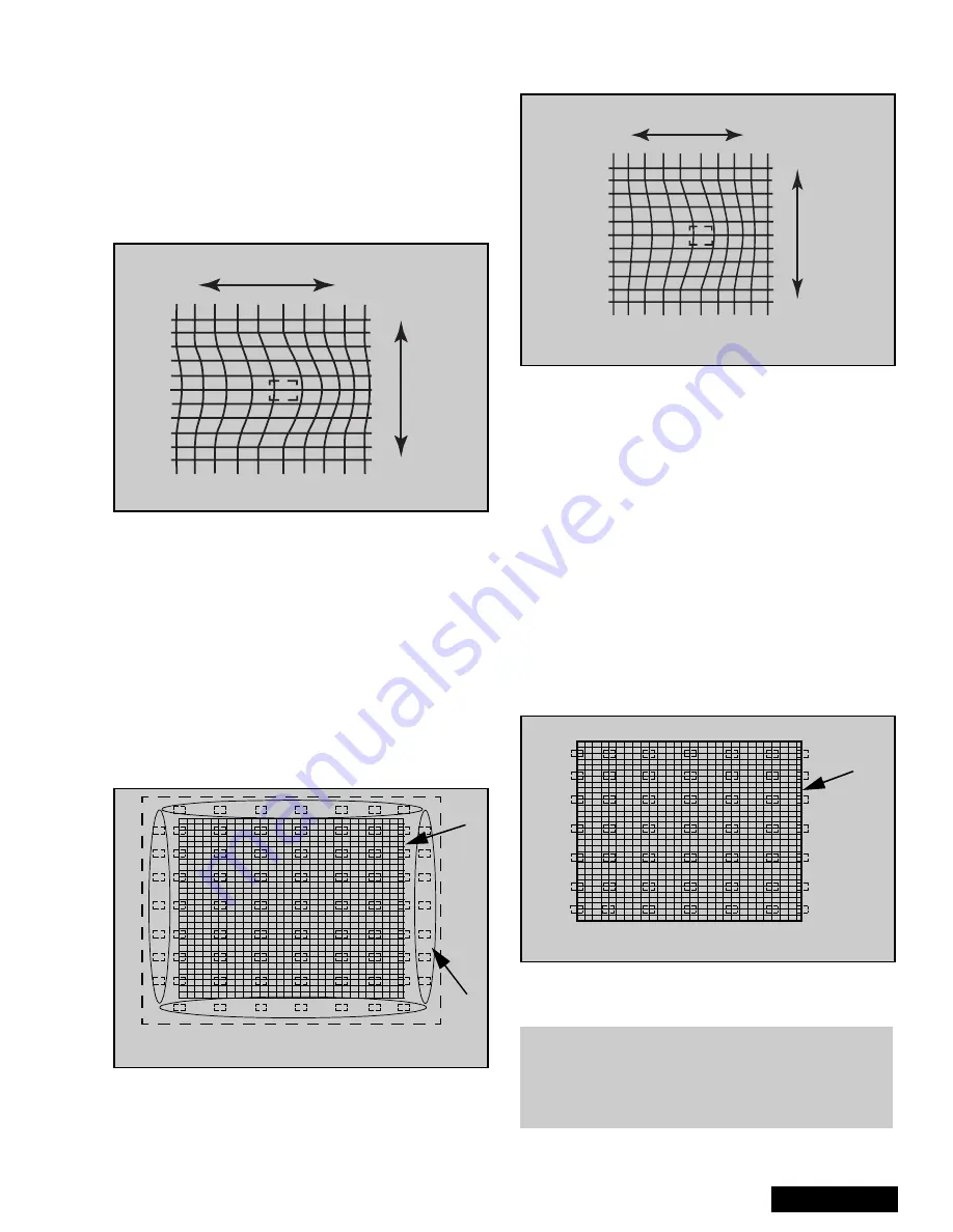
This mode afects a wide area around the cursor
than other adjustment modes, See values on
screen by pressing RECALL on remote
(seeFigure 47)
8.
Begin adjustment from the center to the edge of
the screen.
9.
Adjust by pressing CH up/down and VOL right/lef
on the remote control when the cursor is not
blinking, if the cursor is blinking press MUTE on the
remote.
10. To move the cursor press MUTE on the remote
(cursor blinks), then move the cursor to any of the
9 positions for “EASY” mode(see Figure 46)
11. This adjustment may help to make rounded lines
become straight lines
12. Adjust to make lines as straight as possible
13. Enter to POINT “G-POINT” (for green) mode by
pressing TV/VIDEO.
14. “POINT” mode allows to move line horizontally and
vertically from the perimeter of cursor making
rounded lines become straight (See Figure 48)
15. In “POINT” mode, the adjustment data changes by
2 steps, See values on screen by pressing
RECALL on remote.
16. When the cursor is located in the outer area of the
border the cursor starts to blink from one side to
other and the adjustment is for the non-visible area
(inside the ovals area, see Figure 48); This applies
to “LINE”, “POINT” & “ORIGIN. POINT” modes.
17. Begin adjustment from the center to the edge of
the screen.
18. Adjust to make lines as much straight as possible
19. When slightly adjustment is needed, use “ORIG.
POINT” mode.
20. To enter to “G-ORIG. POINT” (for green) mode
press TV/VIDEO.
21. With “ORIG. POINT”, the adjustment data changes
by 1 step, this allows more detail in the adjustment.
See values on screen by pressing RECALL on
remote
22. Confirm that green adjustment is good enough, if
adjustment is not satisfactory, repeat adjustments.
23. Enter to LINE “G-LINE” mode by pressing TV/
VIDEO.
24. LINE mode allows to move each single line
horizontally and vertically (See Figure 51).
25. Begin adjustment from the center to the edge of
the screen (see Figure 50)
26. Adjust to make distribute lines
27. Then press “1 or 3” on the remote until red and
green appears.
Figure 47. EASY adjustment
left/right
up/down
Figure 48. POINT & ORIG. POINT cursor positions
Cursor
Blinks
Screen
Frame
Figure 49. POINT & ORIG. POINT adjustment
left/right
up/down
Figure 50. LINE adjustment cursor Positions
Screen
Frame
Note: Since convergence adjustment will not
allows to adjust every single cross section
of the grid, it is very important to adjust, so
that overall looks best.
Содержание PT- 56WX51CE
Страница 25: ... 25 Service Manual G Board K Board Schematics G Board Schematic K Board Schematic ...
Страница 26: ... 26 Service Manual G Board K Board PCB G Board PCB K Board PCB ...
Страница 27: ... 27 Notes ...
Страница 28: ... 28 Printed in USA K01062205PL0627 ...
Страница 56: ... 28 A BOARD SCHEMATIC DIAGRAMA ELÉCTRICO TARJETA A A BOARD TARJETA A ...
Страница 57: ... 29 A BOARD SCHEMATIC DIAGRAMA ELÉCTRICO TARJETA A A BOARD TARJETA A ...
Страница 58: ... 30 A BOARD SCHEMATIC DIAGRAMA ELÉCTRICO TARJETA A A BOARD TARJETA A ...
Страница 59: ... 31 A BOARD SCHEMATIC DIAGRAMA ELÉCTRICO TARJETA A A BOARD TARJETA A ...
Страница 61: ... 33 Notes ...
Страница 62: ... 34 Printed in USA K01052203ZR0511 ...
Страница 111: ... 49 ALL MODELS D Board Layout ...
Страница 112: ... 50 ALL MODELS D Board Schematic Left Portion ...
Страница 113: ... 51 ALL MODELS D Board Schematic Right Portion ...
Страница 114: ... 52 ALL MODELS A Board Schematic Left Portion ...
Страница 115: ... 53 ALL MODELS A Board Schematic Left Middle Portion ...
Страница 116: ... 54 ALL MODELS A Board Schematic Right Middle Portion ...
Страница 117: ... 55 ALL MODELS A Board Schematic Right Portion ...
Страница 118: ... 56 ALL MODELS DH Board Schematic ...
Страница 125: ... 63 Notes ...
Страница 126: ... 64 Printed in USA K01052205PL0518 ...


