Panasonic PT-50LC13 - 50

22

For assistance, please call : 1-888-VIEW PTV(843-9788)

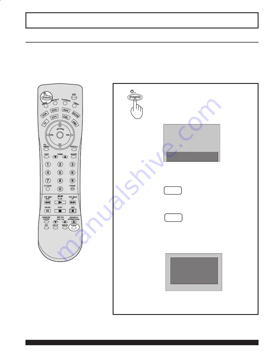
Press the  POWER button to turn the 
projection display on.
(Refer to page 23 for “Turning the Power 
ON and OFF”.)

Automatic Channel Setting is performed.

First, check the connection of the Plug to the Wall Outlet and the Antenna/Cable to the RF in Terminal.
(PP. 12-14.)

If using Cable Box, DSS Receiver, or VCR,

•  Turn on Cable Box.
•  Turn off DSS Receiver, or VCR.

 Case 1

 Case 2

When setup is complete, the lowest 
channel picture appears.

If setup is incomplete, the following 
screen appears. Check connection of 
Antenna/Cable to the RF in Terminal, 
then try Automatic Channel Setting 
again. (PP. 26-27)

Note:

When the unit is turned on for the 

fi

 rst time, Automatic Channel Setting is performed.

Initial Setup

Note:

To cancel AUTO SET in progress, press the 
SWAP button.

Power ON and OFF

 CH AUTO SET PROCEEDING


NO CH FOUND

 PLEASE CHECK ANTENNA

 CABLE CONNECTION THEN

 PRESS ACTION KEY AGAIN

Содержание PT-50LC13 - 50" Rear Projection TV

Страница 1: ...fication is required under the Consumer Product Safety Act 3 Improved Product Development Help us continue to design products that meet your needs Register online at www panasonic com register For assistance please call 787 750 4300 or visit us at www panasonic com Puerto Rico Models No As an ENERGY STAR Partner Matsushita Electric Corporation of America has determined that this product or product...

Страница 2: ...e only with the cart stand tripod bracket or table specified by the manufacturer or sold with the apparatus When a cart is used use caution when moving the cart apparatus combination to avoid injury from tip over 13 Unplug this apparatus during lightning storms or when unused for long periods of time 14 Refer all servicing to qualified personnel Servicing is required when the apparatus has been da...

Страница 3: ...no special notation has been made of company or product trademarks these trademarks have been fully respected Equipped with TV Noise Reduction for true MTS reproduction TV Noise Reduction is required for good stereo separation and audio fidelity is a registered trademark and is licensed by Technology Licensing WARNING AS WITH ANY SMALL OBJECT SD CARDS CAN BE SWALLOWED BY YOUNG CHILDREN DO NOT ALLO...

Страница 4: ...correct the interference by one or more of the following measures Reorient or relocate the receiving antenna Increase the separation between the equipment and receiver Connect the equipment into an outlet on a circuit different from that to which the receiver is connected Consult the dealer or an experienced radio TV technician for help FCC CAUTION To assure continued compliance and prevent undesi...

Страница 5: ...Setup 22 Turning the Power ON and OFF 23 Flow Chart of Main menu 24 Tuning channels 26 Automatic channel setting 26 Manual channel setting 28 Projection display operation 30 ASPECT Controls 32 Searching for the desired channel Channel search 34 Playing peripheral equipment 35 Mute Freeze SAP 36 Split screen 38 Picture in Picture PIP Screen 40 Adjusting screen position and size 42 Audio Adjustments...

Страница 6: ...should utilize 75 Ω coaxial shielded cables Cables are available from your dealer or electronic supply house Before you purchase any cables be sure you know what type of output and input connectors your various components require Also determine the length of cable you ll need Safety Precaution Please take safety precautions to prevent the unit from falling over Viewing position Side view Top view ...

Страница 7: ...s use new batteries when replacing the old set 2 Do not mix battery types example Zinc Carbon with Alkaline 3 Do not attempt to charge short circuit disassemble heat or burn used batteries 4 Battery replacement is necessary when the remote control acts sporadically or stops operating the projection display set Two AA size Remote Control Battery Installation 1 Remote Control EUR7603ZB0 2 Batteries ...

Страница 8: ...on of Controls PIP MIN P 41 SD P 35 PIP MAX P 41 FREEZE P 36 PIP SPLIT CH Down PP 39 41 PIP SPLIT CH Up PP 39 41 CH Search P 34 PIP P 40 SPLIT P 38 PIP MOVE P 41 PIP SPLIT SWAP PP 39 41 DVD Digital Versatile Disc Mode Selection for Remote Control VCR Mode Selection for Remote Control TV Mode Selection for Remote Control Digital TV Mode Selection for Remote Control AUX Mode Selection for Remote Con...

Страница 9: ...el down Returns to normal viewing from the MENU screen Previous before item in MENU SAP button Changes the audio mode P 37 Display menu Press the ACTION button to display Menu screen Note This section describes TV mode only For other modes see pages 69 75 2 1 H C C B A L A M R O N O E R E T S P A S O N O M When the Menu screen is displayed PP 24 25 Moves cursor to the left during menu mode Moves c...

Страница 10: ...he lamp unit P 76 TEMP indicator This indicator lights up when there is an abnormal temperature in the unit P 76 Remote Control Sensor POWER button POWER indicator P 23 Volume up down buttons P 30 Channel up down buttons P 31 Location of Controls Open A A SD CARD slot PC CARD slot Using your finger slide Slot Cover in direction of arrow to open Slot Cover Model PT 50LC13 unit shown ...

Страница 11: ... blocked This could cause damage Location of Controls Vent Component signal input 1 4 terminals P 16 AV out terminals P 17 Input 1 2 terminals P 15 RGB Input 1 terminal PP 18 19 Digital Input terminal P 20 SIDE Input 3 terminals P 15 RGB Input 2 terminal PP 18 19 Model PT 50LC13 unit shown ...

Страница 12: ...ny connections If the cables necessary for connecting a component to the system are not included with the component or available as an option you may need to fashion a cable to suit the component concerned Read the instruction manual for each system component carefully before connecting it If there is a lot of jitter in the video signal input from the video source the picture on the screen may fli...

Страница 13: ... box is required for proper reception Check with your local Cable company for its compatibility requirements For reception of cable channels 01 125 connect the cable supplied by your local cable company Antenna Mode must be set to CABLE P 26 Or Installation CABLE BOX TERMINAL ON THE BACK OF THE CABLE BOX In from cable Connect the cable from the antenna or cable system to the VHF UHF terminal on th...

Страница 14: ...box or VCR set the TV channel to CH3 or CH4 This does not apply when signal is input from VIDEO INPUT Connecting the Antenna Cable to the RF in Terminal VCR Or Installation Connect the cable from the Output terminal on the back of the Cable Box or antenna cable system to the Antenna input terminal on the back of the VCR VCR Incoming Cable from Antenna or Cable TV System TO VCR In from cable TERMIN...

Страница 15: ... 2 3 input terminals Input 3 is located on the side of the unit Select the desired VIDEO input position by pressing the TV VIDEO button P 35 When connecting video cables priority is given to the S Video cable when the S Video input terminal and the video input terminal are connected at the same time Similar connections are available at the INPUT 1 2 3 input terminals P 11 Installation S VHS VCR S ...

Страница 16: ...e color reproduction The Component signal output terminal indication will differ according to the output device Y PB PR Please read the operating instructions included with the output device Installation DVD Player COMPONENT VIDEO AUDIO Mode type Signal data Information menu display No of dots H X V Horizontal frequency kHz Vertical frequency Hz DTV Format Signals 480i 664 X 485 15 73 29 97 480 i ...

Страница 17: ...same video recorder as this could cause incorrect operation Even if TV is in Split or PIP mode OUT terminals only output the main picture and sound signals A sub picture including channel search etc will not be output VIDEO OUT terminals will not output Y PB PR RGB DIGITAL IN or SD PC card signals The S Video OUT terminal outputs the same signal that is input from the S Video IN terminal Or Instal...

Страница 18: ...quality with the projection display a vertical scanning frequency of 60 Hz is recommended Do not set the horizontal and vertical scanning frequencies for PC signals which are above or below the specified frequency range Select the desired RGB input position by pressing the PC MENU or TV VIDEO button P 35 Similar connections are available at the RGB IN 1 2 Terminals Pin No Signal name 1 R 2 G 3 B 4...

Страница 19: ... Connecting a DTV Decoder to RGB IN RGB cable D SUB 15P Audio cable Notes Select the desired RGB input position by pressing the PC MENU or TV VIDEO button P 35 Similar connections are available at the RGB IN 1 2 Terminals M3 stereo mini pin DTV Decoder ...

Страница 20: ... to the DIGITAL IN terminal of this projection display high definition pictures can be displayed on the screen in their digital form This terminal is for use in the future when High bandwidth Digital Content Protection DTV decoders DVD players and D VHS are put on the market DVI cable Notes Select the DIGITAL input position by pressing the TV VIDEO button P 35 The DIGITAL IN terminal can only be u...

Страница 21: ...ired after the projection display is connected to the PC Installation Mode type Signal data Information menu display No of dots H X V Horizontal frequency kHz Vertical frequency Hz Personal Computer Signals VGA400 70 Hz 640 X 400 31 47 70 08 VGA400 70Hz VGA480 60 Hz 640 X 480 31 47 59 94 VGA 60Hz Macintosh 13 640 X 480 35 00 66 67 MAC 13 VESA400 85 Hz 640 X 400 37 86 85 08 VESA 85Hz VESA480 72 Hz ...

Страница 22: ...rn on Cable Box Turn off DSS Receiver or VCR Case 1 Case 2 When setup is complete the lowest channel picture appears If setup is incomplete the following screen appears Check connection of Antenna Cable to the RF in Terminal then try Automatic Channel Setting again PP 26 27 Note When the unit is turned on for the first time Automatic Channel Setting is performed Initial Setup Note To cancel AUTO S...

Страница 23: ...s POWER on projection display or remote control to turn power off Note When the AC Cord is unplugged the internal cooling fan stops operating In this case the lamp will be insufficiently cooled and will take a while to turn ON again Power ON Power OFF The Power Indicator blinks Red for about 1 minute and then turns solid Red Turning the Power ON and OFF POWER button POWER indicator Power ON OFF LE...

Страница 24: ...r go to next menu screen Pressing the ACTION button displays the MENU screen Note Depending on the signal being input some items may or may not be adjustable and some functions may or may not be available 1 Flow Chart of Main menu ADJUST SET UP PICTURE AUDIO POSITION SIZE INFORMATION PAGE SELECT END ADJUST SET UP LANGUAGE ENGLISH CHANNEL LOCK CAPTION VIDEO OTHER PAGE SELECT END ...

Страница 25: ...ST COLOR TEMP NORMAL SELECT EXIT AUDIO AUDIO MENU NORMAL AUDIO ADJUST SPEAKER ON SURROUND OFF BBE OFF SELECT EXIT POSITION H POSITION V POSITION H WIDTH SHRINK NORMAL ADJUST SELECT EXIT INPUT SIGNAL NTSC EXIT ADJUST SET UP LANGUAGE ENGLISH CHANNEL LOCK CAPTION VIDEO OTHER PAGE SELECT END SET UP CHANNEL ANTENNA CABLE AUTO SET MANUAL SET CHANNEL CAPTION WEAK SIGNAL DISPLAY OFF SELECT EXIT CAPTION CA...

Страница 26: ...ctions 1 2 3 Channels will automatically advance until all channels have been scanned Channel numbers with a video signal present will be stored in the channel scan memory Automatic channel setting Continued on the next page Note To cancel AUTO SET in progress press the SWAP button Tuning channels ADJUST SET UP LANGUAGE ENGLISH CHANNEL LOCK CAPTION VIDEO OTHER PAGE SELECT END SET UP CHANNEL ANTENN...

Страница 27: ... can be deleted manually using the MANUAL SET feature 4 Case 1 Case 2 When setup is complete the lowest channel picture appears If setup is incomplete the screen at right appears Check connection of Antenna Cable to the RF in Terminal then try Automatic Channel Setting again Press to exit menu 5 Tuning channels NO CH FOUND PLEASE CHECK ANTENNA CABLE CONNECTION THEN PRESS ACTION KEY AGAIN ...

Страница 28: ... select SET UP Press to select CHANNEL Press to display the CHANNEL Press to select TV or CABLE Press to select ANTENNA 1 2 Manual channel setting Continued on the next page ADJUST SET UP LANGUAGE ENGLISH CHANNEL LOCK CAPTION VIDEO OTHER PAGE SELECT END SET UP CHANNEL ANTENNA CABLE AUTO SET MANUAL SET CHANNEL CAPTION WEAK SIGNAL DISPLAY OFF SELECT EXIT SET UP CHANNEL ANTENNA CABLE AUTO SET MANUAL ...

Страница 29: ...rom memory Press to exit menu Note Some channels with very weak signals may be locked into memory If desired these channels can be deleted manually using the MANUAL SET feature 5 6 To add channel To delete channel Tuning channels MANUAL SET ENTER CHANNEL 01 CHOOSE A CHANNEL USING CHANNEL UP DOWN DELETE EXIT MANUAL SET ENTER CHANNEL 01 CHOOSE A CHANNEL USING CHANNEL UP DOWN ADD EXIT ...

Страница 30: ...operate the projection display with the remote control 1 2 3 4 Notes The channel number and volume level are stored even after the projection display is turned off Power consumption can be reduced if the volume level is lowered Or Remote Control Sensor POWER button POWER indicator Volume up down buttons Channel up down buttons 0 Note Refer to Using the number keys on the next page Projection displ...

Страница 31: ...layed to display current TV status information Example 2 To select channel 12 press the 1 key then 2 Channel 12 appears momentarily Example 3 To select channel 8 press the 8 key Channel 8 appears momentarily FREEZE Invalid operation notification If an invalid operation is attempted the mark shown right is displayed Projection display Channel up down buttons can also be used to select an outside in...

Страница 32: ...with the aim of displaying programs for a commercial purpose or for public presentation please note that by using the aspect ratio 16 9 selection function to change the aspect ratio you may be infringing on the rights of the original copyright owner of that program under copyright protection laws If a normal 4 3 picture is projected in wide screen distortion may occur around the edges so that part...

Страница 33: ...splay a 4 3 picture at maximum size but with aspect correction applied to the center of the screen so that elongation is only apparent at the left and right edges of the screen The size of the picture will depend on the original signal ZOOM ZOOM 16 9 ZOOM mode magnifies the central section of the picture FULL FULL 16 9 FULL will display the picture at its maximum size but with sight elongation TRU...

Страница 34: ...n order When it reaches the right bottom the next channel is displayed at the left top overwriting the previously displayed channel Notes To end channel search press SEARCH OPEN CLOSE While using the PIP feature Channel search is not available 0 Example Select channel 6 0 CH03 02 05 06 08 10 07 RGB1 02 05 06 07 10 08 RGB input Searching for the desired channel Channel search Channel up and down bu...

Страница 35: ...VIDEO 2 Signal of source connected to INPUT 2 is displayed VIDEO 3 Signal of source connected to INPUT 3 is displayed COMPONENT 1 Signal of source connected to COMPONENT VIDEO INPUT 1 is displayed COMPONENT 2 Signal of source connected to COMPONENT VIDEO INPUT 2 is displayed COMPONENT 3 Signal of source connected to COMPONENT VIDEO INPUT 3 is displayed COMPONENT 4 Signal of source connected to COM...

Страница 36: ...ction can be switched between a frozen still picture and a moving picture each time the FREEZE button on the remote control unit is pressed Press FREEZE button again to resume motion Sound mute Useful when answering the phone or receiving unexpected visitors Freezing pictures E Z E E R F E T U M Note The audio output from AV OUT is not muted Note The video output from AV OUT is not frozen Mute Fre...

Страница 37: ...udio mode If stereo broadcast is weak and the display flickers select MONO audio mode for possibly better results SAP broadcast Secondary Audio Program sub language Select SAP audio mode for the sub language MONO broadcast Normal monaural sound broadcast Receivable Broadcast Types 2 1 H C O E R E T S P A S O N O M 2 1 H C P A S O N O M O E R E T S 2 1 H C P A S O N O M O E R E T S 2 1 H C P A S O ...

Страница 38: ... can change the input change channels and adjust the volume The right and left screens cannot display the same picture at the same time A split screen which includes an RGB DIGITAL IN signal is fixed as SPLIT SCREEN NORMAL Example RGB input is shown right CARD input screen cannot be displayed using the Split Screen function Splitting the screen Press to split The previously selected screen appears...

Страница 39: ...y change the input Finally press SWAP button again to change the screen back to the right Press to select the desired channel PIP buttons can also be used to select an outside input for the right side of the screen No input mode is displayed for terminals with no equipment connected CH05 RGB1 CH05 RGB1 Example During SPLIT SCREEN NORMAL RGB input Note Picture quality may change according to the co...

Страница 40: ...rminal Because Main and PIP screens are processed by individual circuits image quality may vary slightly PIP mode returns to single screen when the projection display is turned off The Main and PIP screens cannot display the same picture at the same time An RGB DIGITAL IN signal and CARD input screen cannot be displayed using the PIP screen function A component signal cannot be displayed on a PIP ...

Страница 41: ... the screen size for PIP screen You can choose PIP screen size of 3 magnifications Press to large PIP screen size Note PIP buttons can also be used to select an outside input for the PIP screen Initial size 0 Initial position 0 Note The last size chosen is saved and will not be erased even if the power is turned off Note The last position chosen is saved and will not be erased even if the power is...

Страница 42: ...ess to exit menu Press to select the menu to set each item NORMAL is displayed at default FULL mode Adjusting screen position and size ADJUST SET UP PICTURE AUDIO POSITION SIZE INFORMATION PAGE SELECT END POSITION H POSITION V POSITION H WIDTH SHRINK NORMAL ADJUST SELECT EXIT POSITION H POSITION V POSITION V SIZE NORMAL ADJUST SELECT EXIT POSITION H POSITION V POSITION H SIZE PHASE NORMAL ADJUST S...

Страница 43: ...rned off The signals output from the monitor output terminal on the back of the projection display is not affected when the screen size and position is adjusted Adjusting screen position and size Adjustment item Button Adjustment Details Note H Position Press button The image moves to the right Press button The image moves to the left V Position Press button The image moves up Press button The ima...

Страница 44: ...he units two front speakers Surround sound effect is not available for normal mono broadcasts You can turn off the internal speakers when it is connected to external audio equipment Notes Sound signals are output from the rear AUDIO OUT terminal When volume is adjusted or the mute button is pressed from the remote control a message will be displayed Press to exit menu Audio Adjustments AUDIO AUDIO...

Страница 45: ...is set to AUTO or if BBE is ON BASS and TREBLE cannot be adjusted BBE sound technology enhances speech intelligibility and restores the dynamic range of musical passages to provide outstanding natural sound Press to exit menu 4 Note If BBE is ON SURROUND cannot be selected Audio Adjustments AUDIO ADJUST BASS TREBLE BALANCE NORMAL ADJUST SELECT EXIT AUDIO AUDIO MENU NORMAL AUDIO ADJUST SPEAKER ON S...

Страница 46: ...ress to select the menu to set each item Press to set each item Press to exit menu Normal color Displays unaltered image During RGB DIGITAL IN input COLOR TEMP changes to NORMAL Picture Adjustments ADJUST SET UP PICTURE AUDIO POSITION SIZE INFORMATION PAGE SELECT END PICTURE PICTURE MENU DYNAMIC PICTURE ADJUST COLOR TEMP NORMAL SELECT EXIT PICTURE PICTURE MENU DYNAMIC PICTURE ADJUST COLOR TEMP NOR...

Страница 47: ...or levels are adjusted Except RGB DIGITAL IN Press button Picture intensity becomes weaker as both contrast and color levels are adjusted SHARPNESS Press button The picture quality becomes sharper Except RGB DIGITAL IN Press button The picture quality becomes softer CONTRAST Press button Only the Highlights of the image become brighter adding Contrast RGB DIGITAL IN only Press button The Highlight...

Страница 48: ...cret code 3 Press to save 4 digit code Notes Once ratings are set restricted tapes or programs cannot be accessed unless the secret code is entered If you forget your secret code refer to Reset User s Memory Functions on page 51 Changing your secret code You will need your current code Press to clear current code Repeat step 2 to enter new code Press to display LOCK menu for rating screen and go t...

Страница 49: ...O Cannot view NR programs YES Can view NR programs ON V Chip Control is activated OFF V Chip Control is deactivated Press to set Note Ratings highlighted in Red will be blocked while those not highlighted black letters will not be blocked Lock Feature LOCK ENTER 4 DIGIT CODE ENTER 0 9 EXIT LOCK 1 2 US MOVIES OFF CHANGE SETTINGS US TV PROGRAMS OFF CHANGE SETTINGS SELECT EXIT LOCK 1 2 US MOVIES OFF ...

Страница 50: ...l not be blocked You may select from standard TV ratings chart 1 or customize to a specific content rating chart 2 ON V Chip Control is activated OFF V Chip Control is deactivated VIEW NR Not Rated PROGRAMS NO Cannot view NR programs YES Can view NR programs Lock Feature VIEW NR PROGRAMS YES TV Y UNLOCKED TV Y7 FV TV G TV PG V S L D TV 14 V S L D TV MA V S L CONTAINS NO RATING SELECT EXIT LOCK 1 2...

Страница 51: ...me materials may not be suitable for children PG 13 PARENTS CAUTIONED Some materials may be inappropriate for children under 13 R RESTRICTED Children under 17 must be accompanied by a parent or adult NC 17 OVER AGE 17 ONLY No one 17 and under admitted X ADULTS ONLY Blocking Message US MOVIES RATINGS TV Y FOR ALL CHILDREN Content specifically geared to young viewers ages 2 6 TV Y7 FOR AGE 7 AND OLD...

Страница 52: ...N button to display the MENU screen and select SET UP Press to select CAPTION Press to display the CAPTION screen Press repeatedly to select CAPTION MODE Press to select CAPTION MODE Press to exit menu 3 This receiver has a built in decoder that provides a visual depiction of the audio portion of a television program in the form of written words across the screen white or colored letters on a blac...

Страница 53: ...press the MUTE button again Note This feature functions when the Closed Caption Mode is in the OFF position The program being viewed must be broadcast with Closed Caption Notes The setting for CC ON MUTE is valid only when the CC MODE is OFF CC MODE set to ON will override CC ON MUTE Closed Caption is not displayed if the input signal is COMPONENT VIDEO INPUT of 480P or more or from RGB DIGITAL IN...

Страница 54: ... to move cursor to the right Press to select a station Repeat step 3 and 4 until the Caption List is complete 4 Press to set Press to select channel number To remove a registered channel number select the station then press the button CLEAR To make a correction press the button Channel Caption Feature SET UP CHANNEL ANTENNA CABLE AUTO SET MANUAL SET CHANNEL CAPTION WEAK SIGNAL DISPLAY OFF SELECT E...

Страница 55: ...splay the SET UP CHANNEL screen Press to set ON or OFF Press to select WEAK SIGNAL DISPLAY Press to exit menu 3 Note If unit is connected to equipment which has blue back feature selecting ON will have no effect on the other equipment When ON is selected the picture is displayed even when a broadcast signal is weak or non existent Weak Signal Display Feature SET UP CHANNEL ANTENNA CABLE AUTO SET M...

Страница 56: ...e event of weak signal conditions the Video NR circuitry reduces noise in the luminance channel It is important to note that Video NR should remain OFF for maximum picture detail when receiving a strong signal or viewing high quality video Note When an RGB DIGITAL IN signal is input VIDEO NR is set to OFF only Video NR Noise Reduction Feature ADJUST SET UP LANGUAGE ENGLISH CHANNEL LOCK CAPTION VID...

Страница 57: ...NENT VIDEO INPUT Adjust 480p signals to achieve a natural color from digital equipment connected to COMPONENT VIDEO INPUT Y PB PR input terminals 1 2 Press the ACTION button to display the MENU screen and select SET UP SDTV When the input signal is a normal TV system NTSC HDTV When the input signal is a High Definition system HD Press to select VIDEO Press to display the VIDEO screen Press to sele...

Страница 58: ... s RGB IN or DIGITAL IN terminal Most of analog RGB DIGITAL IN signals are selected automatically When RGB DIGITAL IN input signal is VGA 60Hz from PC or 480P from other equipment you must manually switch to the desired input RGB DIGITAL IN Input Feature ADJUST SET UP LANGUAGE ENGLISH CHANNEL LOCK CAPTION VIDEO OTHER PAGE SELECT END VIDEO VIDEO NR OFF ID 1 OFF 480P COLOR MATRIX SDTV RGB VGA 3D Y C...

Страница 59: ...O NR OFF ID 1 OFF 480P COLOR MATRIX SDTV RGB VGA 3D Y C ON 3D IP ON SELECT EXIT 3D Y C Feature 3D IP Feature 1 2 Press the ACTION button to display the MENU screen and select SET UP ON Recordings created at 24 frames per second are shown in higher quality OFF Set to OFF if picture appears unnatural Film media taken at 24 frames per second is faithfully reproduced on the projection display Press to...

Страница 60: ...Press to select SLEEP TIMER Press to exit menu 3 The projection display can be set to shut itself off at a preselected time ADJUST SET UP LANGUAGE ENGLISH CHANNEL LOCK CAPTION VIDEO OTHER PAGE SELECT END OTHER SLEEP TIMER OFF DEMO MODE OFF SELECT EXIT OFF 30min 60min 90min Sleep Timer Feature Note Pressing RECALL with sleep timer set displays remaining time Minutes remaining is displayed for the l...

Страница 61: ...displays follow the instructions below Information Press the ACTION button to display the MENU screen and select ADJUST 1 Press to select INFORMATION Press to display INFORMATION screen You can display the input signal type Display items differ depending on the input signal 2 Press to exit menu ADJUST SET UP LANGUAGE ENGLISH CHANNEL LOCK CAPTION VIDEO OTHER PAGE SELECT END ADJUST SET UP PICTURE AU...

Страница 62: ...or OFF Press to select DEMO MODE Press to exit menu 3 Function demonstrations of this unit are displayed in Demo mode ADJUST SET UP LANGUAGE ENGLISH CHANNEL LOCK CAPTION VIDEO OTHER PAGE SELECT END OTHER SLEEP TIMER OFF DEMO MODE OFF SELECT EXIT ON Demo mode is started OFF Demo mode is canceled Note Demo mode setting remains even when power is turned off To turn off Demo mode select DEMO MODE OFF ...

Страница 63: ...this unit The SD Card and PC Card are precision devices Do not subject them to excessive pressure or strong impacts ROOT DCIM P1000001 jpg P1000002 jpg P1000003 jpg P1000004 jpg P1010001 jpg P1010002 jpg P1010003 jpg P1010004 jpg 100_PANA 101_PANA Folders and Files DCIM Folder The digital camera creates this folder automatically Example If the Card file hierarchy is displayed on the PC as shown in...

Страница 64: ...be displayed SD Card slot PC Card slot SD Card Compact Flash Multi Media Card Smart Media Memory Stick xD Picture Card Compatible Card Front Card Slot P 10 SD Card Press PC Card EJECT TAB twice The media listed in the right column above can be read via the PC Card in the PC Card adaptor Hard disk PC Cards Flash ATA Cards and other recorded media cannot be used Place the selected media onto the PC ...

Страница 65: ...older Make changes to the parent previous directory display Select a Subfolder Display files folders contained in the folder Index Area Operation 1 2 Press to select MENU Press to move to index area Press to set Press to select icon MENU PAGE 1 6 SINGLE SLIDE SD PC MENU PAGE 1 6 SINGLE SLIDE SD PC SD PC When both an SD Card and PC Card are inserted the buttons can be used to select a card in the i...

Страница 66: ...file in INDEX AREA Press to display next previous page of 9 thumbnail files Press ACTION to display file in full screen size MENU PAGE 1 6 SINGLE SLIDE SD PC Press The next image is displayed Press The previous image is displayed Press Each press rotates image 90 Continued in left column of next page SINGLE VIEW SCREEN Press Press Press Press Press Press Press Press Press ...

Страница 67: ...GE 1 6 SINGLE SLIDE SD PC START SPEED FAST TRANSITION NORMAL 2 Press RECALL with SINGLE VIEW screen displayed to return to the Index Area menu When ACTION is pressed while the Information Screen is displayed the Picture Adjust menu p 46 is displayed Rotation angle is maintained Press ACTION to stop or resume slide show Note If a file name exceeds 8 characters a file name different from the origina...

Страница 68: ...d interrupting the power line by using circuit breakers or switchable power strips Due to the characteristics and use conditions of individual lamps the lamp may cease to light before the stated lamp life Influences of frequent lighting continuous light use for over 24 hours the number of times lit the length of time between lightings etc may shorten lamp life Because of this we recommend having a...

Страница 69: ...your remote is set for this code Then press the Remote Control POWER button to test the component If the procedure was successful the component will turn on Notes Due to changes in infra red commands used by manufacturers some brands have several codes If your unit does not respond to the first code please try the next one If an incorrect number is entered or there is an incomplete entry after 30 ...

Страница 70: ...s Once the code has been found press the ACTION button to lock it in Notes The step and set mode will start from the current device not the beginning of the library except for the first time The step and set mode works in the reverse direction using the button Infrared Remote Codes for Specific Components Helpful Hint Write down the code numbers for your components in the space provided below This...

Страница 71: ...HILIPS 323 324 331 CITIZEN 306 PIONEER 323 CRAIG 305 306 329 PROSCAN 300 301 302 323 324 331 333 345 346 CURTIS MATHES 324 345 QUASAR 321 322 323 324 DAEWOO 301 324 343 RADIO SHACK 305 309 324 333 336 340 DBX 310 311 339 RCA 300 301 302 323 324 331 333 345 346 DIMENSIA 345 REALISTIC 305 309 324 336 340 EMERSON 303 319 320 325 326 343 SAMSUNG 302 304 333 FISHER 305 307 308 309 313 SANSUI 320 326 33...

Страница 72: ...OWAY 106 PHILIPS 106 107 128 129 130 VIEWSTAR 129 130 PIONEER 101 116 ZENITH 100 117 ZENITH DRAKE SATELLITE 100 Remote Control Quick Reference Guide Operating peripheral equipment Maker List DVD Maker Set Up No Maker Set Up No DENON 100 SABA 101 FERGUSON 101 SAMSUNG 110 JVC 109 SHARP 108 MITSUBISHI 105 SONY 104 NORDMENDE 101 TECHNICS 100 PANASONIC 100 THOMSON 101 PHILIPS 103 TOSHIBA 103 PIONEER 10...

Страница 73: ...VR Maker Set Up No Maker Set Up No ADMIRAL 120 OPTIMUS 103 127 130 131 AIWA 125 126 PANASONIC 118 119 121 DENON 134 135 136 PHILIPS 123 FISHER 104 PIONEER 105 107 GARRARD 113 QUASAR 118 119 121 HARMAN KARDON 115 123 RCA 103 105 127 130 131 JENSEN 129 SANSUI 103 111 139 JVC 132 133 SHARP 134 137 KENWOOD 100 108 SONY 122 MAGNAVOX 127 SOUNDESIGN 138 MARANTZ 124 TEAC 111 112 113 MCLNTOSH 116 TECHNICS ...

Страница 74: ...p Down Navigation Up Down Navigation Up Down Next Previous Track Volume Navigation Left Right ACTION TV DTV CBL DBS DVD TV Menu DTV Menu Enter DBS Menu Select DVD DTV DBS DVD Menu Menu On Off Menu On Off PAGE DBS DVD Page Up Down Skip R TUNE TV CBL VCR DBS DTV AUX Cassette Deck Previous Channel Previous STB Channel Deck A B RECALL TV VCR DBS DVD DTV CD Onscreen Display Onscreen Display Time Format...

Страница 75: ...lay Play TV VCR AUX Cassette Deck DVD CD RCVR SPLIT function PIP Size Fast Forward Fast Forward Skip Search Fast Forward Skip Search Fast Forward Surround TV VCR AUX Cassette Deck CD DVD Freeze Pause Pause Still TV VCR DVD CD AUX Cassette Deck PIP Swap SPLIT swap Stop Stop Stop Stop TV DTV VCR AUX Cassette Deck DBS Channel Search Info EPG Record Record Record VCR DBS TV VCR switch TV DBS switch TV...

Страница 76: ...or When using a VCR and selecting channels on the TV is the TV VIDEO mode for the VCR set to TV Image appears doubled or tripled Is the antenna facing the right direction Is the antenna receiving any signals reflected off of mountains or buildings Images disappear at the top and bottom of the screen When using 16 9 image software there is no picture at the top and bottom of the screen cinema visio...

Страница 77: ...EO 1 0 Vp p 75 Ω RCA Pin Jack S VIDEO Y 1 Vp p 75 Ω C 0 286 Vp p 75 Ω Mini DIN 4 pin AUDIO L R 0 5 Vrms RCA Pin Jack x 2 COMPONENT VIDEO INPUT 1 4 Y 1 0 Vp p with sync 75 Ω Pin Jack PB PR 0 35 Vp p 75 Ω Pin Jack x 2 AUDIO L R 0 5 Vrms RCA Pin Jack x 2 DIGITAL IN INPUT DIGITAL IN DVI 1 0 24 pin AUDIO L R 0 5 Vrms RCA Pin Jack Type 2 Card slot SD Card slot SD Card Multi Media Card PC Card slot Compa...

Страница 78: ...ture screen Customer Services Directory Cleaning For Product Information Operating Assistance Literature Request Dealer Locations and Customer Service inquiries please visit Web Site http www panasonic com You can purchase parts accessories locate your nearest servicenter and more by visiting our Web Site or E mail us via web http www panasonic com consumer_electronics support customerfeedback asp...

Страница 79: ... diagnosis and or repair and then returned Limited Warranty Limits And Exclusions This warranty ONLY COVERS failures due to defects in materials or workmanship and DOES NOT COVER normal wear and tear or cosmetic damage The warranty also does not cover damages which occurred in shipment or failures which are caused by products not supplied by the warrantor or failures which result from accidents mi...

Страница 80: ...inals 11 B BBE 45 Blocking Message 51 C Card MENU SCREEN 64 Channel up down buttons projection display 10 30 CH buttons remote control 9 24 Component signal input terminals 11 D Digital Input terminal 11 DIGITAL IN position 35 DVI cable 20 F Freezing pictures 36 Function buttons 8 I ID 1 57 Input 1 2 3 terminals 11 L LAMP indicator 10 Left screen 38 Light button 9 M Main picture 38 40 Main screen ...

Отзывы: