ACCTF1E-4
2017.04
industrial.panasonic.com/ac/e/
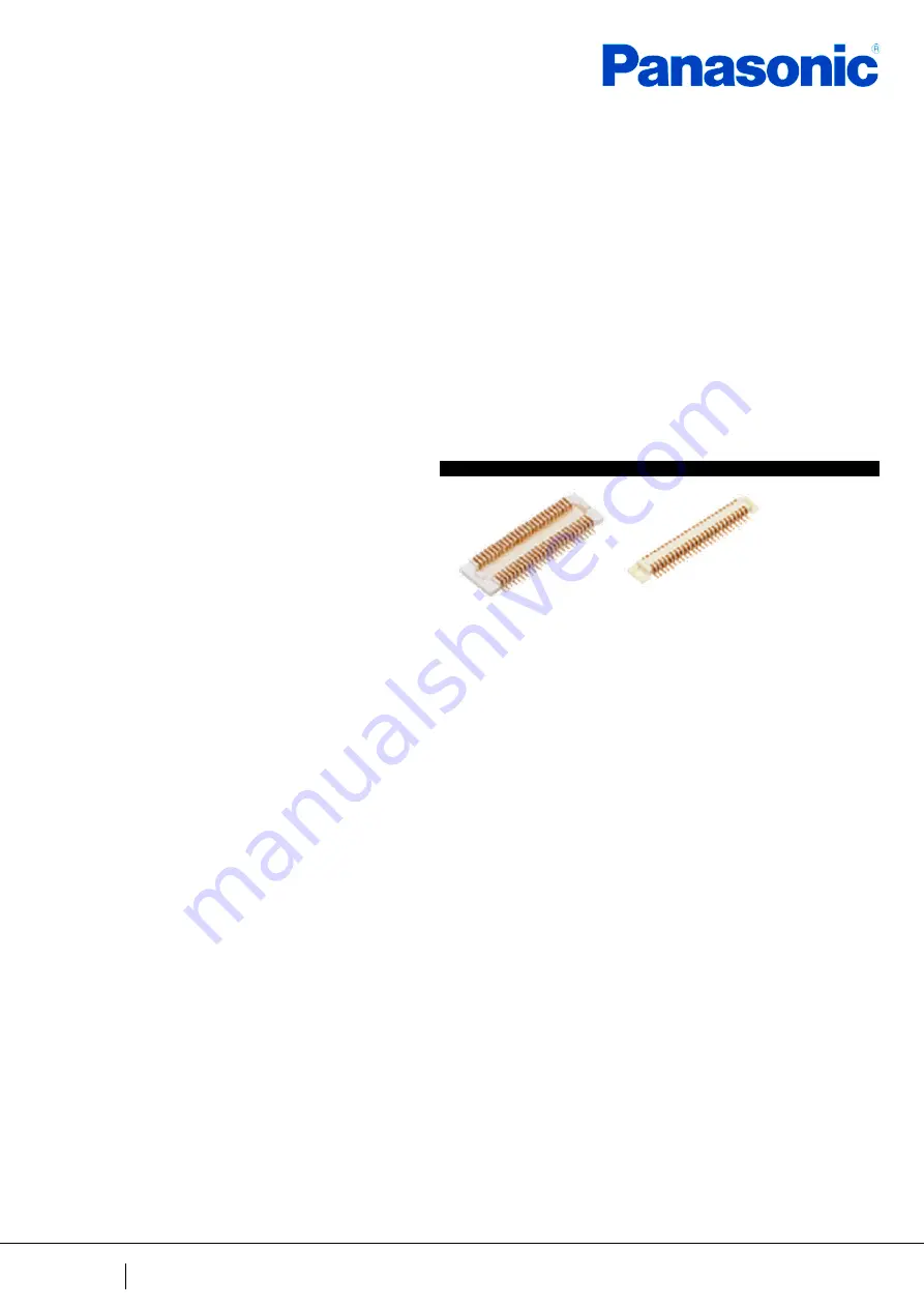
P5KF
Narrow-pitch Connectors
Operation manual
Страница 1: ...ACCTF1E 4 2017 04 industrial panasonic com ac e P5KF Narrow pitch Connectors Operation manual ...
Страница 2: ...dustrial panasonic com ac e Panasonic Corporation 2017 ACCTF1E 4 201704 1 Contents 01 Introduction 2 02 Precautions for equipment design 3 03 Precautions during mounting to reflow 13 04 Precautions for mating 19 Parts that require special confirmation are bold and underlined ...
Страница 3: ...n The P5KF narrow pitch connector has a terminal pitch of 0 5 mm and stacking height of 1 5mm This connector is designed for parts requiring space reduction For this purpose the molded part has been downsized and made thinner Select models best suited to the situation and conditions of use Read this document before designing the equipment and starting production ...
Страница 4: ...ned connector positions may cause mating failure or product breakage Panasonic corporation does not guarantee the failures caused by using the multiple connectors 2 Solid board is tend to warp to vertical direction against mill direction of production process Some warp directions can cause poor soldering Therefore arrange the board in a direction that can minimize warp This gap causes poor solderi...
Страница 5: ... of problems during equipment operations 1 Although this product is equipped with a simple locking mechanism insert cushioning material in the equipment enclosure in order to prevent the header from being detached from the socket or damaged during operation Please consider that there should be no gap between the enclosure and the board It is recommended that holding force to the sub board be bigge...
Страница 6: ...there is no gap between enclosure and sub board A B the sub board strikes against the enclosure Due to the impact of its strike the connector is affected and might be damaged Prevention Please fix the both main and sub board sufficiently 1 Fix the main board Fix the side that has the larger mass and prevent the inertial motion of drop impact 2 Hold with object such as rubber cushion not to move by...
Страница 7: ...l cause poor solder at the terminal section 3 Please control the insulation coating thickness resist thickness on the pattern surface The coating thickness can ordinarily be controlled to the µm level If the thickness is too great it will press up on the connector bottom and will cause terminal poor solder 4 Be sure to consult with us beforehand if you want to perform through hole wiring on the bo...
Страница 8: ...ge is more likely to occur if a pattern is laid in a line or if the copper foil is applied over the entire FPC board for noise prevention purposes It is difficult to keep FPC flat because FPC is flexible Example of carrier for mounting process Magic resin Daisho Denshi Silicon gum board Mitsubishi Resin Assist carrier ShinEtsu Polymer Co Ltd When mounting connector it is recommended that the usage...
Страница 9: ...layer Generally the coverlay thickness is set to about 30 μm including the adhesive If the thickness exceeds 30 μm remove the coverlay under the connector from the design 3 This connector can be used for main board to FPC connection In case that the flexible board is too short excessive load affects the connector and may be shifted out Please design as the flexible board is appropriately slack Con...
Страница 10: ...plates will warp during reflow soldering and cause poor soldering It is recommended to cut the material in the direction of the reinforcing fiber 4 In order to achieve greater device thinness methods that use metals such as stainless steel are used for support plates when extremely thin support plates are desired 5 Design the support plates so that the edges are 0 5 1 0 mm or more outside the tips...
Страница 11: ... sure to adjust the amount of solder applied after checking the finish quality in a test run 2 Compared with natural air reflow soldering N2 reflow soldering can reduce oxidization of the melted solder surface This significantly improves the solder wettability Therefore please make sure to apply an appropriate amount of solder 3 Do not apply an excessive amount of solder otherwise solder or flux m...
Страница 12: ... Recommended specifications of mounting pattern on PC board and window size of metalmasking Product Narrow pitch connector P5KF series socket Part No AXK5F Recommended mounting pattern on PC board Top view Recommended window size of metalmasking Top view Thickness of metalmasking 150μm Window ratio 56 Thickness of metalmasking 120μm Window ratio 69 ...
Страница 13: ... Recommended specifications of mounting pattern on PC board and window size of metalmasking Product Narrow pitch connector P5KF series header Part No AXK6F Recommended mounting pattern on PC board Top view Recommended window size of metalmasking Top view Thickness of metalmasking 150μm Window ratio 58 Thickness of metalmasking 120μm Window ratio 72 ...
Страница 14: ...nectors Even if you select a high speed mounter please use a multi function head and load control 03 2 Precautions for selecting a pickup nozzle for mounting connectors Select a pickup nozzle with a pickup area that provides a theoretical lift force 10 times greater than the connector s weight Theoretical lifting force gr Vacuum pressure mmHG 760 1 033 Nozzle area cm2 Sample vacuum pressure of mac...
Страница 15: ...es the contact section or its periphery it is possible that the amount of solder applied was excessive or that wicking has occurred In this case check the amount of solder applied and the temperature at the connector mounting position Special care is required with an N2 reflow oven 4 Larger front fillets can be achieved by extending the screen opening outward and shifting the solder application po...
Страница 16: ...ring solder rework solder should be supplied at and the soldering iron should be applied to the tip of each pattern trace on the PC board in order to minimize contact with the terminals 3 When carrying out manual soldering or solder rework avoid using flux if possible in order to prevent it from rising to the contact section For details see the next page 4 When using flux apply as little as possib...
Страница 17: ...t of solder to be applied is recommended e g BON 102F made by Japan Bonkote Co Ltd 2 Selection of soldering iron for lead free solder in particular Recommendation for 0 5 mm narrow pitch connectors Cutter blade shaped iron tip BJ7 KF made by Japan Bonkote Co Ltd Iron tip with a temperature sensor Temperature controllable iron tip In addition it is necessary to check whether or not the displayed ir...
Страница 18: ... iron tip on the foot pattern along the terminals without touching them Apply the soldering iron to the foot pattern to heat it Complete soldering in 1 or 2 seconds Connector s resistance to soldering heat 300 C 5 sec max 350 C 3 sec max Thin wire solder with a diameter of 0 3 0 4 mm is recommended Final soldering is recommended after provisionally soldering the terminals at both ends Note that wh...
Страница 19: ...ons prepare equipment for cleaning process beginning with boil cleaning ultrasonic cleaning and then vapor cleaning 2 Carefully oversee the cleanliness of the cleaning fluids to make sure that the contact surfaces do not become dirty from the cleaning fluid itself 3 Since some powerful cleaning solutions may dissolve molded components of the connector and wipe off or discolor printed letters we re...
Страница 20: ...ts during mating and slanted mating may result in contact buckling and deformation so please perform mating work according to the following procedure Procedure 1 Position the child board block so there is a rough match between the socket and header mating positions 2 Move the child board block gently to the left and right and up and down and check that the mating positions of the socket and header...
Страница 21: ...on Molded part resin breakage generation of cutting dust contact defects due to interposition in the contact section spring section return defects due to broken resin In mating of dual sided boards in particular be careful because it is difficult to check the positioning state of the socket header Slanted mating Mating by pressing in when the Socket and header mating openings are misaligned Mating...
Страница 22: ...ration 2017 ACCTF1E 4 201704 21 04 2 Precautions during detachment Please work so that the connector is as parallel as possible during detachment When detaching a connector mounted to an FPC perform the detachment action while holding the reinforcement panel so that detachment is not done by holding the FPC Good Wrong ...
Страница 23: ...dustrial panasonic com ac e Panasonic Corporation 2017 ACCTF1E 4 201704 22 Amendment history Manual No Date Changes ACCTF1E 1 October 2013 Company name and format change ACCTF1E 2 June 2015 Division name change ACCTF1E 3 March 2016 Revised P 3 ACCTF1E 4 April 2017 Revised P 3 ...
Страница 24: ...ACCTF1E 4 201704 2017 ...