


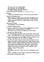


If the Horizontal Position of the Audio Control Head is not
properly adjusted, a maximum envelope cannot be obtained at the
Neutral Position of the Tracking Control Circuit.
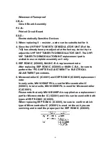
1. Insert the alignment tape.
2. Press and hold FF button and CH DOWN buttons on VCR together
over 5 seconds in power off condition.
The power comes on and the unit goes into service mode.
3. Play back the alignment tape.
4. To enter Tracking center mode, press PLAY button in Play back
mode. "TRACKING CENTER" will be displayed on the TV monitor.
5. Connect the oscilloscope to TP3002 on the Video Signal Process
Section of the Main C.B.A. Use TP6205 as a trigger.
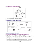
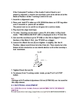
6. Loosen the Black Screw (D) and tighten it slightly. Set the H-
Position Adjustment Driver into the Hole (A). Then slowly turn the
fixture either clockwise or counterclockwise so that the envelope
is at maximum.
Fig. M7
7. Tighten Black Screw (D).
8. To release from Tracking center mode, press PLAY or STOP
button.
Note:
Old type of H-Position Adjustment Driver (VFK0136) can be used for
this adjustment.
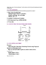
6.3. ELECTRICAL ADJUSTMENT
6.3.1. EVR (Electronic Variable Resister) ADJUSTMENT WITH THE REMOTE
CONTROL
This unit has electronic technology using I2C Bus concept.The PG SHIFTER ADJUSTMENT is
43
Содержание NV-SJ4130PN
Страница 6: ...Fig 1 4 Fig 1 5 6 ...
Страница 22: ...5 2 3 EJECT Position Confirmation Fig J1 2 22 ...
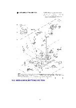
Страница 48: ...10 2 MECHANISM BOTTOM SECTION 48 ...
Страница 49: ...10 3 CASSETTE UP COMPARTMENT SECTION 49 ...
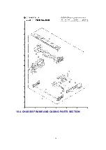
Страница 50: ...10 4 CHASSIS FRAME AND CASING PARTS SECTION 50 ...
Страница 51: ...10 5 PACKING PARTS AND ACCESSORIES SECTION 51 ...
Страница 56: ...11 2 MECHANICAL REPLACEMENT PARTS LIST MECHANICAL REPLACEMENT PARTS 56 ...
Страница 96: ......
Страница 97: ......