


1.2. ABOUT LEAD FREE SOLDER (PbF)
The lead free solder has been used in the mounting process of all electrical components on the printed circuit boards used for this
equipment in considering the globally environmental conservation.
The normal solder is the alloy of tin (Sn) and lead (Pb). On the other hand, the lead free solder is the alloy mainly consists of tin
(Sn), silver (Ag) and Copper (Cu), and the melting point of the lead free solder is higher approx.30 degrees C (86°F) more than that
of the normal solder.
Definition of PCB Lead Free Solder being used
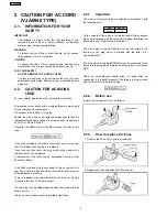
The letter of “PbF” is printed either foil side or components side on the PCB using the lead free solder.
(See right figure)
Service caution for repair work using Lead Free Solder (PbF)
·
The lead free solder has to be used when repairing the equipment for which the lead free solder is used.
(Definition: The letter of “PbF” is printed on the PCB using the lead free solder.)
·
To put lead free solder, it should be well molten and mixed with the original lead free solder.
·
Remove the remaining lead free solder on the PCB cleanly for soldering of the new IC.
·
Since the melting point of the lead free solder is higher than that of the normal lead solder, it takes the longer time to melt
the lead free solder.
·
Use the soldering iron (more than 70W) equipped with the temperature control after setting the temperature at 350±30
degrees C (662±86°F).
Recommended Lead Free Solder (Service Parts Route.)
·
The following 3 types of lead free solder are available through the service parts route.
RFKZ03D01K-----------(0.3mm 100g Reel)
RFKZ06D01K-----------(0.6mm 100g Reel)
RFKZ10D01K-----------(1.0mm 100g Reel)
Note
* Ingredient: tin (Sn), 96.5%, silver (Ag) 3.0%, Copper (Cu) 0.5%, Cobalt (Co) / Germanium (Ge) 0.1 to 0.3%
5
NV-GS230EG
Содержание NV-GS230E
Страница 2: ...2 NV GS230EG ...
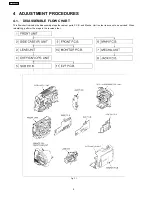
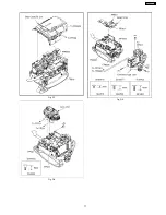
Страница 10: ...Fig D3 Fig D4 Fig D5 Fig D6 10 NV GS230EG ...
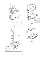
Страница 11: ...Fig D7 Fig D8 Fig D9 11 NV GS230EG ...
Страница 12: ...Fig D10 Fig D11 Fig D12 Fig D13 12 NV GS230EG ...
Страница 13: ...Fig D14 Fig D15 Fig D16 Fig D17 13 NV GS230EG ...
Страница 14: ...Fig D18 Fig D19 Fig D20 Fig D21 14 NV GS230EG ...
Страница 15: ...Fig D22 Fig D23 15 NV GS230EG ...
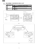
Страница 17: ...Fig M3 17 NV GS230EG ...
Страница 18: ...Fig M4 Fig M5 18 NV GS230EG ...
Страница 19: ...Fig M6 19 NV GS230EG ...
Страница 22: ...How to use extension cables Fig T1 22 NV GS230EG ...
Страница 26: ...Fig E3 Rough image of set up connection 26 NV GS230EG ...
Страница 27: ...Fig E4 Extension cables VFK1317 2pcs Measuring Board VFK1308E 232C I F Cable VFK1395 27 NV GS230EG ...
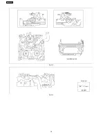
Страница 31: ...Fig D2 Fig D3 31 NV GS230EG ...
Страница 44: ...NV GS230EG 44 ...
Страница 50: ...NV GS230EG 50 ...
Страница 51: ...12 EXPLODED VIEWS 12 1 FRAME CASING SECTION 1 51 NV GS230EG ...
Страница 52: ...12 2 FRAME CASING SECTION 2 52 NV GS230EG ...
Страница 53: ...12 3 LCD SECTION 53 NV GS230EG ...
Страница 54: ...12 4 CAMERA LENS SECTION 54 NV GS230EG ...
Страница 55: ...12 5 VCR MECHANISM SECTION 55 NV GS230EG ...
Страница 56: ...12 6 PACKING PARTS ACCESSORIES SECTION 56 NV GS230EG ...


