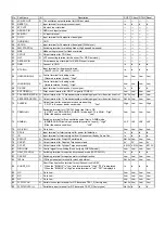
No.
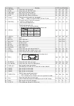
Port Name
I/O
Description
P-OFF
P-Save
P-FAIL Reset
1
CURRENT_LIMIT
O Capstan motor current limit terminal.
Low
Low
Low
Low
2
F ADJUST
O Analogue voltage output for HEAD frequency response adjustment
Low
Low
Low
Low
3
N.C.
-- Low fix (No Connection.)
Low
Low
Low
Low
4
C EMPHA(H)
O
Terminal of the Current emphasis video/FM audio recording current.
[HIFI/2HEAD ]:Fix to Low (Normal mode)
[4HEAD]
:Fix to Low (factory mode)
Fix to High (Insert/AV Insert mode)
Others (Depend on tape speed)
Low
Low
Low
Low
5
TRACKING_ENVE
O Playback envelope input for auto tracking adjustment and cvc.
In
In
In
In
6
SLP(H)
O
Tape running speed output terminal.(Output signal depens on tape speed)
[High]………During NTSC_10H or PAL_9H mode
[Low ]………Except NTSC_10H or PAL_9H mode
Low
Low
Low
Low
7
LP(H)
O
Tape running speed output terminal.(Output signal depens on tape speed)
[High]………During NTSC_4H/6H or PAL_6H/9H mode
[Low ]………Except NTSC_4H/6H or PAL_6H/9H mode
2HEAD model: Low Fix
Low
Low
Low
Low
8
CPB
I
Input terminal for "PB (H)" from AV2.
[High]………3.85V - 5.0V
[Midd]………1.82V - 2.84V
[Low ]……… 0V - 0.81V
In
In
In
In
9
AFC S
I
"S-curve" Input terminal from tuner.
In
In
In
In
10
A-MUTE(H)
O Audio mute output terminal for RF Converter.
High
High
Low
High
11
AV1_8IN
I
Input terminal for "PB (H)" from AV1.
[High]………3.85V - 5.0V
[Midd]………1.82V - 2.84V
[Low ]……… 0V - 0.81V
In
In
In
In
12
N/S/T2/T3
I
Mode select terminal
[NORMAL mode ]: More than 4.0V
[SERVICE mode]: 2.5V - 4.0V
[TEST_2 mode ]: 1.0V - 2.5V
[TEST_3 mode ]: 0V - 1.0V
In
In
In
In
13
S-PHOTO
I
Tape end sensor input terminal.(Photo sensor input from supply side)
[Black Tape]: more than 2.6V
[Lead Tape]: Less than 2.4V
In
In
In
In
14
T-PHOTO
I
Tape beginning sensor input terminal.(Photo sensor input from take-up side)
[Black Tape]: more than 2.6V
[Lead Tape]: Less than 2.4V
In
In
In
In
15
ABS_NORM(H)
I
(Input terminal for FM audio enverope output level detection)
In
In
In
In
16
N.C
-- Low fix (No Connection.)
Low
Low
Low
Low
17
PLAY_REC(L)
O
Output terminal for switching the capstan voltage.
[Other than PLAY/REC mode]……………Always "High".
[JOG/Shuttle mode in PLAY mode ]……Always "High".
After 5 seconds from PLAY/REC mode completion, it changes to "Low".
During "Low" outputs, it checks every main capstan FG, when the no FG is
inputted in a rotation, it changes to "High" and it keeps "high" by cassette ejection.
Low
Low
Low
Low
18
VSYNC(L)
O
Output terminal for V_sync detection result.
[Vsync exist] : "Low"
[Vsync not exist: "High"
Low
Low
Low
Low
19
D.FM.REC(H)
O Timing output terminal for FM_Audio recording current.
Low
Low
Low
Low
20
ART.V/H/N
O Output terminal for Artificial V synchronization signal.
Low
Low
Low
Low
Содержание NV-FJ632EE
Страница 1: ...ORDER NO VRD0203011C2 Video Cassette Recorder NV FJ632EE Z MECHANISM SPECIFICATIONS 1 ...
Страница 7: ...7 ...
Страница 10: ...5 install the Cylinder Stator Unit 6 Tighten 2 screws A Fig S7 10 ...
Страница 21: ...4 REMOVAL OF THE MAIN C B A Remove 4 screws F Unlock 4 Tabs G Fig D5 21 ...
Страница 23: ...5 SERVICING POSITION Fig D7 23 ...
Страница 29: ...3 3 8 CIRCUIT BOARD LAYOUT 4 ABBREVIATIONS 29 ...
Страница 45: ...D1207 11EQS04 DIODE B0JAME000020 45 ...

