1. INTRODUCTION
This service manual contains technical information which will allow service personnel to
understand and service this model.
If the circuit is changed or modified, this information will be followed by supplementary service
manual to be filed with original service manual.
Note:
1. Adjustment procedures, Disassembly Procedures and Assembly
Procedures for Mechanism Chassis are separate volume from this
service manual. / Please refer to the service manual for Z-
Mechanism Chassis. (Order No. VRD9802005C2)
2. The Model No. is indicated on the Schematic Diagram and Circuit
Board Diagrams as follows.
Model No.
Indication Mark
NV-FJ625EG
(A)
NV-FJ625EGY
(B)
NV-FJ625B
(C)
NV-FJ625EC/ECM/ECN
(D)
NV-FJ625ECY
(E)
2. GENERAL DESCRIPTIONS
2.1. SERVICE CAUTION
2.1.1. REPLACING IC7702/EEPROM
When the EEPROM: IC7702 is replaced, applicable model code, option code and electrical
adjustment data will not be available.
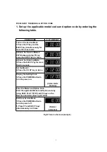
Therefore, enter and/or adjust the necessary data after replacing IC7702 by referring following
procedure.
STEP1.REPLACE THE IC7702
1. Remove the C.B.A. with Mechanism unit by referring the
Disassembly procedure.
2. Disconnect the AC plug and replace the IC7702.
2
Содержание NV-FJ625EG
Страница 23: ...10 2 CASING PARTS SECTION 23 ...
Страница 24: ...10 3 PACKING PARTS SECTION 24 ...
Страница 25: ...11 REPLACEMENT PARTS LIST 11 1 CHASSIS PARTS SECTION PARTS LIST 25 ...
Страница 38: ...C7620 ECUX1C104ZFV C CAPACITOR CH 16V 0 1U 38 ...
Страница 40: ...D7503 RB441P DIODE 40 ...


