IMPORTANT NOTICE
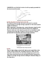
The following components have potentials above 2000V while the
appliance is operated.
- Magnetron
- High voltage transformer (Located on inverter (U))
- High voltage diodes (Located on inverter (U))
- High voltage capacitors (Located on inverter (U))
Pay special attention to these areas.
When the appliance is operated with the door hinges or magnetron
fixed incorrectly, the microwave leakage can exceed more than
5mW/cm
2
. After repair or exchange, it is very important to check if
the magnetron and the door hinges are correctly installed.
2.7. Sharp edges
Caution
Please use caution when unpacking, installing or moving the unit,
as some exposed edges may be sharp to the touch and cause
injury if not handled with care.
3. MEASUREMENTS AND ADJUSTMENTS
3.1. Adjustment of primary latch switch, secondary latch switch and
short switch.
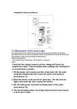
1. Mount the Primary latch switch, the secondary latch switch and
the short switch to the door hook assembly as shown in ILL.
NOTE:
No specific individual adjustment during installation of the
Primary latch switch, secondary latch switch or short switch to
the door hook are required.
2. When mounting the door hook assembly to the oven assembly,
adjust the door hook assembly by moving it in the direction of the
arrows in the illustration, so that the oven door will not have any
play in it. Check for play in the door by pulling the door assembly.
Make sure that the latch keys move smoothly after adjustment is
completed. Completely tighten the screws holding the door hook
assembly to the oven assembly.
3. Reconnect the short switch and check the continuity of the
monitor circuit and all latch switches again by following the
Содержание NN-T703QF
Страница 3: ......
Страница 4: ......
Страница 5: ......
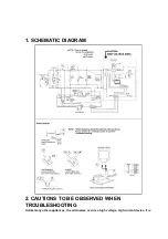
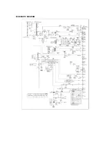
Страница 18: ...SCHEMATIC DIAGRAM ...
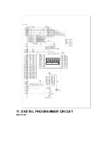
Страница 19: ...11 DIGITAL PROGRAMMER CIRCUIT PARTS LIST ...


