background image

167

[Reference]

Reference

command

1

mode

1

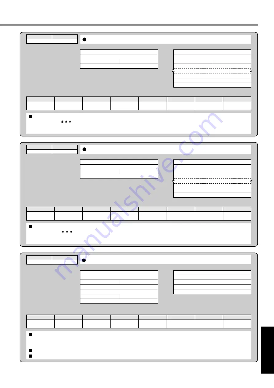
Setting of RS232C protocol parameters

Received data

3

axis

T1
T2

checksum

1

1

RTY

M/S 

Error code

Transmitted data

Setting of the previous protocol parameters remains valid until execution of this command completes.  The updated parameter setting will be 

valid from a next command after execution of this command.  

M/S=0 indicates "SLAVE" mode, while M/S=1 indicates "MASTER".

The RTY code is 4 bit and M/S is 1 bit.

Unit of T1 and T2 are 0.1 second and 1 second, respectively.

bit7

0 : Normal
1 : Error

6

5

Command error

4

3

RTY error

2

T2 error

1

T1 error

0

M/S error

1

axis

Error code

checksum

1

1

command

0

mode

5

Readout of the driver model name

Received data

0

axis

checksum

0

5

Error code

Transmitted data

    The driver model name is 12 characters and transmitted by ASCII code.    
ex.  "MKDET1505           "

bit7

0 : Normal

1 : Error

6

5

Command error

4

3

2

1

0

0Dh
axis

Driver Model Name (high order)

Driver Model Name (low order)

Error code

checksum

0

5

command

0

mode

6

Readout of the motor model name

Received data

0

axis

checksum

0

6

Error code

Transmitted data

    The motor model name is 12 characters and transmitted by ASCII code.    
ex.  "MUMA012P1           "

bit7

0 : Normal

1 : Error

6

5

Command error

4

3

2

1

0

0Dh
axis

Motor Model Name (high order)

Motor Model Name (low order)

Error code

checksum

0

6

Buy: www.ValinOnline.com | Phone 844-385-3099 | Email: [email protected]

Содержание Minas E Series

Страница 1: ...g Panasonic AC Servo Motor Driver MINAS E series Before using this driver please read this manual especially refer the safty precautions page 8 to 11 to ensure proper use Then keep this manual for your future use Buy www ValinOnline com Phone 844 385 3099 Email CustomerService valin com ...

Страница 2: ...g of Main Circuits 27 Wiring of Connector CN X4 Connection with Encoder 29 Wiring of Connector CN X5 Connection with Host Controller 30 Wiring of Connector CN X6 Connection with Personal Computer Console 31 Timing Chart 32 Holding Brake 35 Dynamic Brake DB 36 Homing Operation Precautions 38 Setting the Parameters 39 Overview of Parameters 39 How to Set 39 Overview of Console 39 Overview of PANATER...

Страница 3: ...Parameter for Selection of Functions 88 Parameters for Adjustment of Time Constants of Gains Filters 91 Parameters for Auto Gain Tuning 92 Parameters for Adjustment Related to Second Gain Switching Function 94 Parameters for Position Control 95 Parameters for Internal Velocity Control 98 Parameters for Torque Limits 99 Parameters for Sequences 99 Connections and Settings in Internal Velocity Contr...

Страница 4: ...osition Control 121 Parameters for Internal Velocity Control 122 Parameters for Torque Limits 123 Parameters for Sequences 123 Adjustment Page Gain Adjustment 128 Objective of Gain Adjustment 128 Types of Gain Adjustment 128 Procedures of Gain Adjustment 129 Real time Auto Gain Tuning 130 Normal Auto Gain Tuning 132 Cancellation of the Automatic Gain Tuning 135 Manual Gain Tuning Basic 136 Manual ...

Страница 5: ... 184 Recommended Parts 192 Dimensional Outline Drawing Driver 193 Dimensional Outline Drawing Motor 194 Allowable Load of Output Shaft 196 Motor Characteristics S T Characteristics 197 Servo Motor with Gear 198 Dimensional Outline Drawing of Motor with Gear 200 Allowable Load of Output Shaft of Servo Motor with Gear 202 Characteristics of Servo Motor with Gear S T Characteristics 203 Driver Intern...

Страница 6: ...6 MEMO Buy www ValinOnline com Phone 844 385 3099 Email CustomerService valin com ...

Страница 7: ...r Opening the Package 14 Model of Driver 14 Model of Motor 15 Check the Combination of Driver and Motor 15 Parts Description 16 Driver 16 Motor 16 Console 17 Installation 18 Driver 18 Motor 20 Console 22 Page Before Use Buy www ValinOnline com Phone 844 385 3099 Email CustomerService valin com ...

Страница 8: ...is prohibited to do Indicates that the operation must be done Do not subject the product to water corrosive or flammable gases and combustibles The failure could result in fire Do not expose the cables to sharp objects excessive pressing or pinching forces and heavy loads The failure could result in electric shocks damages or malfunction Do not put your hands in the servo driver The failure could ...

Страница 9: ...onduct the transportation wiring and inspection of the driver The failure could result in electric shocks Install the product properly to avoid personal accidents or fire in case of an earthquake The failure could result in electric shocks injuries or fire Attach the motor driver regenerative resistor to incombustible matter such as metal The failure could result in fire Make sure to secure the sa...

Страница 10: ... result in damages Do not shock the driver and the motor The failure could result in damages Avoid excessive gain adjustments changes or unstable operation of the product The failure could result in injuries Do not use the motor internal brake for the purpose of controlling speed of load The failure could result in injuries or damages Do not approach to the equipment after recovery from the power ...

Страница 11: ...ad unconnected Connect a load to the motor after the successful trial operations The failure could result in injuries Connect a relay that stops at emergency stop in series with the brake control relay The failure could result in injuries or damages If an error occurs remove the causes of the error and secure the safety before restarting the operation The failure could result in injuries Use the e...

Страница 12: ...ing conditions as stated above differ this periodic inspection interval is subject to change Type Daily inspection Periodical inspection Cycles Daily Every year Inspection items Ambient temperature humidity dust particles foreign matters etc Abnormal sound and vibration Main circuit voltage Odor No yarn piece etc adhered to the air hole How the driver front and connector are cleaned Each wired cab...

Страница 13: ...or Cooling fan Bearing Oil seal Encoder Standard replacement cycles hour about 5 years about 5 years Approx 100 000 cycles The life depends on the actual operating conditions Approx 20 000 cycles The life depends on the actual operating conditions 2 to 3 years 10 000 to 30 000 hours 3 to 5 years 20 000 to 30 000 hours 5000 hours 3 to 5 years 20 000 to 30 000 hours 10 000 hours Remarks The replacem...

Страница 14: ...at provides for stable stop performance and contributes to miniaturization of the equipment and reduction of tact time It supports a console available as an option capable of monitoring such as display of rotation speed parameter setting test run JOG operation parameter copying etc and pursues maximum ease for use This document is designed for you to properly and sufficiently use functions of MINA...

Страница 15: ...ut 50W 100W 200W 400W Check the Combination of Driver and Motor This driver is designed for use in combination with a motor to be specified by us Check a name of series rated output voltage specifications and encoder specifications of a motor you wish to use Incremental specification 2500 P r Single phase 100V Single phase 200V Three phase 200V Remarks The marking in Motor Type column of Applicabl...

Страница 16: ...tia Type MUMA Series 50W Encoder Cable Encoder Flange Frame Mounting Holes in 4 locations Motor Cable MUMA 50W 400W x1 x3 x4 x5 x6 STATUS ALM CODE Status LED Alarm Code LED Connector for Serial Communications X6 Interface Connector X5 Encoder Connector X4 Motor Connector X3 Main Power Supply Connector X1 Buy www ValinOnline com Phone 844 385 3099 Email CustomerService valin com ...

Страница 17: ...TTING mode 3 EEPROM WRITE mode 4 NORMAL AUTO GAIN TUNING mode 5 AUXI FUNCTION mode Test run JOG mode Alarm clear 6 COPING FUNCTION mode To copy parameters to the console from the servo driver To copy parameters to the servo driver from the console This is used to shift the digits of data This is used to change the data and to execute parameter selection The numerical value goes up and down by pres...

Страница 18: ...round the driver for ventilation 2 For the mounting dimensions onto the wall face in the board refer to Page 193 of the dimensional outline drawing Installation Item Ambient temperature Ambient humidity Storage temperature Storage humidity Vibration Altitude Conditions 0 to 55 C free from freezing Lower than 90 RH free from condensation 20 to 80 C free from freezing Lower than 90 RH free from cond...

Страница 19: ...haust Direction Fan Driver Exhaust Direction Driver Exhaust Direction Driver Exhaust Direction Driver Intake Direction Driver Intake Direction Driver Intake Direction Driver Intake Direction min 100 mm min 40 mm min 40 mm min 10 mm min 10 mm min 10 mm min 100 mm Part where DIN rail is mounted DIN rail With rail stop pushed in Hook the upper side of DIN rail mounting part on the DIN rail With the r...

Страница 20: ...prevent oil inflow to the motor from the speed reducer In this case the oil sealed motor is a special product 3 For the mounting dimensions refer to a dimensional outline drawing Pages 194 to 195 Oil and Water Protections 1 Don t use the motor under an environment where oil and water splash over the motor body 2 In combining with the speed reducer use the oil sealed motor to prevent oil inflow to ...

Страница 21: ...alue specified for each model 2 In using the rigid coupling take good care of mounting Over bending load on it if any would cause damage wear of the shaft and shorter life of the bearings 3 Use the flexible coupling of possibly high stiffness to control radial load arising from minor center deviation at the permissible value or less 4 For information on allowable load of an output shaft of each ty...

Страница 22: ...he cable with an excessive force Do not set the product near a heat generating device such as heater and large wire wound resistor Method of Connection Remarks Securely connect the console connector to the connector CN X6 of the driver Never connect or disconnect the connector by grabbing the connector cable Item Ambient temperature Ambient humidity Storage temperature Storage humidity Vibration S...

Страница 23: ...2 Holding Brake 35 Dynamic Brake DB 36 Homing Operation Precautions 38 Setting the Parameters 39 Overview of Parameters 39 How to Set 39 Overview of Console 39 Overview of PANATERM 39 How to Connect 40 Parameter Groups and Listing 41 Using the Console 47 Using the Console 47 The initial State of the Display 7 segment LED 47 Structure of Each Mode 48 Monitoring Mode 51 Parameter Setting Mode 57 Nor...

Страница 24: ... in the main power 5 Pins 3 Pins of CN X1 When using the driver for an application of large regenerative energy connect an external regenerative resistor between P 5 pins and B 3 pins of connector CN X1 Install an external regenerative resistor on incombustible material such as metal and provide the regenerative resistor with a protective device such as temperature fuse etc to prevent the resistor...

Страница 25: ...uch as PLC etc Motor cable Power supply for motor brake 24 V DC Junction cable for motor Junction cable for brake Wiring to Connector CN X3 Connection with each phase of motor windings pply L1 L1 L2 L2 L1 L2 Wiring to Connector CN X4 Connection with encoder Junction cable for encoder MODE SHIFT SET S M MKDET1310P 200V For connections refer to Points in Wiring Page 27 L3 L3 L3 Buy www ValinOnline c...

Страница 26: ...by Matsushita Electric Industrial Co Ltd For compliance with EC Directives don t fail to connect the circuit breaker with LISTED Mark which is authorized and certified under IEC and UL Standards between the power supply and the noise filter Noise filter For DV0P4160 refer to Page 182 Remarks For wiring to the power connector motor connector and earth terminal use the copper conductors of 60 C and ...

Страница 27: ...er Provide the magnetic contactor coil with surge absorber Never start stop the motor by magnetic contactor Install AC reactor For three phase 200V connect L1 10 pints L2 8 pins and L3 6 pins For single phase 100V and 200V connect L1 10 pins and L3 6 pins Connect to the grounding system of the facility Connect the driver protective earth terminal and the protective earth earth plate of the control...

Страница 28: ... L2 L3 P P P MC L MC NFB MC ON OFF ALM N N B U V E W L1 COM 13 12 24V 3 4 Black CN X1 CN X3 CN X5 Noise filter Red Tyco Electronics AMP K K Power supply Tyco Electronics AMP K K White or yellow Green yellow Motor 172167 1 Molex Incorporated 5557 10R 210 Molex Incorporated 5557 06R 210 172159 1 1 2 ALM VDC 9 3 6 4 1 3 5 6 10 ALM L2 L3 P P P MC L MC NFB MC ON OFF N N B U V E W L1 COM 13 12 24V 3 4 B...

Страница 29: ... 0V as illustrated left 6 Connect nothing to the empty terminal NC of the connector Servo motor 2 0V 5V 1 4 5 3 6 Case 5 4 1 2 3 6 Twist pair Junction cable made by Tyco Electronics AMP K K 172160 1 172168 1 made by Tyco Electronics AMP K K Motor side Servo driver side White Light blue Purple Shielded cable Black Regulator 0V 5V 0V 5V TX RX TX RX FG 0V 5V NC TX RX TX RX FG X4 CN 7 Don t use a cabl...

Страница 30: ...s nor be bundled together with them A customer is requested to prepare for power supply for control signals VDC between COM and COM Voltage DC 12 to 24V For such wiring as command pulse input or encoder signal output etc use shielded twist pair cable Neither apply 24V or more to a control signal output terminal nor run 50mA or higher If you directly activate a relay using the control signal output...

Страница 31: ...puter and driver 1 1 through RS 232C and use PANATERM optional component the setup supporting software Running PANATERM on your personal computer you can have convenient functions with excellent operability such as various types of monitors parameter settings changes waveform graphic displays etc 2 You can connect a host personal computer or host controller and driver through RS 232C for communica...

Страница 32: ...d Not input Input 100ms or Longer Approx 700 ms Established Initialize Approx 2 seconds Approx 40 ms Approx 1 5 ms Approx 10 ms Approx 2 seconds OFF After Power ON Receiving Servo ON Signal Cautions The above chart shows timing from AC power ON to command input Enter Servo ON signal and external command according to the above timing chart 1 During this period the SRV ON signal has not been accepte...

Страница 33: ... 1 A value of t1 is a value of Pr6B or time needed for decreasing the motor speed to approx 30 r min whichever is shorter 2 For operation of the dynamic brake following an alarm event also refer to the description in Sequence at Alarm Parameter Setting for every control mode on Pr68 Approx 30r min Alarm Dynamic Brake Motor Energized Normal Energized Not Alarm Error Operation 2 Not Energized Alarm ...

Страница 34: ... input does not become active until it stops 3 For operation of the dynamic brake during Servo OFF also refer to the description of Sequence at Servo OFF Parameter Settings of every control mode on Pr69 4 Servo ON input will not be active until the motor rotation speed falls below approx 30r min Servo ON OFF Operation When the Motor is Stopped During normal operation perform the Servo ON OFF opera...

Страница 35: ...ing sound Chattering etc while it is running But this is not a problem 2 When the current is fed into the brake coil with the brake kept released it could result in leak magnetic flux from the shaft etc Be careful when a magnetic sensor etc are used around the motor Wiring Example This circut shows an example in which a brake release BRK OFF signal from the driver is used to control the brake The ...

Страница 36: ... running provide a lead time of about 3 minutes after complete stop This dynamic brake can be started in the following cases 1 Against Servo OFF 2 When any of the protective functions actuate 3 When the overtravel inhibit inputs CWL CCWL of the connector CN X5 actuate In the above cases 1 3 it is selectable by setting up the applicable parameters whether the dynamic brake is started or put in free...

Страница 37: ...ing deceleration After stop Sequence at Servo OFF Pr69 3 Setting of Driving Conditions through Deceleration and Stop by Enabling Overtravel Inhibit Input CWL CCWL Pr66 D B Free Run Free Run Free Run 0 Setting of Pr66 1 Deceleration and stop set up at overtravel inhibit Pr66 Driving Conditions During deceleration After stop Servo Lock Servo Lock Speed zero clamp Speed zero clamp 2 2 Position contro...

Страница 38: ...s on initialization consider both positioning and initialization when you set them For detailed information on initialization refer to the operating manual for the host controller Example of Homing Operation Proximity dog on When the proximity input turns ON the motor will start to decelerate and stop when a first origin input Z phase is entered Proximity dog off When the proximity input turns ON ...

Страница 39: ...ble to 1 Monitor rotation speed torque positional deviation input output power pulse input load factor etc of servo motors 2 Setup and save parameters of servo motor drivers 3 Write the data into memory EEPROM 4 Execute normal auto gain tuning 5 Indicate current alarms and make reference to error history 6 Operate test runs 7 Make copies of parameters and clear alarms Overview of PANATERM This PAN...

Страница 40: ...sh version For the latest version contact us RS 232C connecting cable DV0P1960 for DOS V Connecting to CNX6 Connecting to CNX6 Console DV0P3690 How to Connect Notes Securely connect the connector with the connector CN X6 of the driver Never insert or pull out the connector while holding a cable Buy www ValinOnline com Phone 844 385 3099 Email CustomerService valin com ...

Страница 41: ...he data related to interchange of 1st gain 2nd gain These parameters are used to set up input form and logical selection of command pulses and dividing of encoder output pulses and to set up the dividing multiplier ratio of command pulses etc These parameters are used to set up internal velocity 1 4 velocity JOG speed acceleration deceleration time etc This parameter is used to set up torque limit...

Страница 42: ... 12 13 14 15 16 17 18 19 1A 1B 1C 1D 1E 1F 26 27 2A 2B 2C Parameters for adjusting the time constants of gain filter Parameter No Parameter description Range Default Unit Related control mode Pr Axis address 7 segment LED for console initial condition display Control mode set up For manufacturer use Overtravel Input inhibit For manufacturer use ZEROSPD TC input selection For manufacturer use Warni...

Страница 43: ...not allowed and any one of parameters functions can only be used By priority a parameter that is entered first will be validated Ex By setting Real time auto tuning parameter 1st notch frequency is set compulsorily to 1500 Invalidated at the driver side even it was input 3 An adaptive filter is only validated in high function positioning control mode Control mode set up 1st notch frequency Damping...

Страница 44: ...or manufacturer use FIR filter set up For manufacturer use 1 4 0 3 0 3 1 16384 0 1 1 10000 1 10000 0 17 1 10000 0 7 0 31 4 0 1 0 2500 0 10000 10000 0 0 10000 1 0 0 0 P r 2n Setup value 1 cycles P P2 P P2 P P2 P P2 S P P2 S P P2 P P2 P P2 P P2 P P2 P P2 40 41 42 43 44 45 46 47 48 49 4A 4B 4C 4D 4E 4F Parameters for Positioning Control Parameter No Parameter description Range Default Unit Related co...

Страница 45: ...that has been written in the driver before the replacement Particularly the setup value needs no change Before replacing motor After having replaced Ex 50W motor had been used with 100 torque limit In the case the current 50W motor is replaced with another 50W motor of the same output capacity Pr5E setup value remains unchanged as 100 torque limit Pr5E 1st torque limit can t be set up in excess to...

Страница 46: ... 256Pulse 2ms 2ms P P2 P P2 S S P P2 P P2 P P2 S P P2 S P P2 S P P2 S P P2 S P P2 S 60 61 62 63 64 65 66 67 68 69 6A 6B 6C 6D 6E 6F Parameters for Sequence Pr63 position over deviation is set up at the over deviation detection value of setup value x 256pulses The default setup value would result in position over deviation error if the value of 1875 x 256pulses is exceeded Parameter No Parameter de...

Страница 47: ...selected Driver ID No 2 digits The value set up on Pr00 shaft name is ID No Parameter No 2 digits is displayed under Parameter Setting mode Setting Button Mode Selector Buttons These buttons are used to select 6 different modes 1 MONITOR mode 2 PARAMETER SETTING mode 3 EEPROM WRITE mode 4 NORMAL AUTO GAIN TUNING mode 5 AUXI FUNCTION mode Test run JOG mode Alarm clear 6 COPING FUNCTION mode To copy...

Страница 48: ...n SET S Mode switch button Selection Display MODE M MODE M MODE M MODE M MODE M MODE M Monitor Parameter setting EEPROM writ Normal auto gain tuning Copy function Auxiliary functions Mode switch button Mode switch button Mode switch button Mode switch button Mode switch button Structure of Each Mode Buy www ValinOnline com Phone 844 385 3099 Email CustomerService valin com ...

Страница 49: ...SET S Set button SET S Set button SET S Set button SET S Execution Display Make a copy of parameters from servo driver to console Make a copy of parameters from console to servo driver For details on parameters refer to Position Control Mode on Page 65 and Internal Velocity Control Mode on Page 103 Buy www ValinOnline com Phone 844 385 3099 Email CustomerService valin com ...

Страница 50: ...ng the proceeding from to If the connector is disconnected during the time by any chance connect the connector again and restart the operation from the beginning After finishing write return to Selection Display referring to Structure of Each Mode Page 48 and 49 MINAS DIGITAL AC SERVO MODE SHIFT SET S M 1 Insert the connector of console into CN X6 of the driver and then turn on the power of the dr...

Страница 51: ...of permissible regenerative power Overload factor 28 Inertia ratio 100 Total feedback pulses 50 Total control pulses 10 Motor auto recognition active RS232C communication P 52 P 52 P 53 P 55 P 56 P 56 P 56 P 56 P 56 P 56 P 56 P 56 P 56 The display shifts in the arrow direction by pressing and in the reverse direction by pressing SET S MODE M Page 57 When power of the servo driver is turned on for ...

Страница 52: ...n viewed from the end of axis Rotation speed of motor r min Indication with CW rotation Without CCW rotation Torque output Rated output 100 Indication with CW rotation Without CCW rotation Data Display of positional deviation rotation speed of motor and torque output Display of control mode Remarks is not indicated with LED Only is indicated Remarks Both high velocity response positioning control ...

Страница 53: ...connected with connector CN X5 is displayed Make use of this display to check the quality of wiring and for other purposes Input signal Output signal No of the lowest place of input signal No of the highest place of input signal No of the lowest place of output signal No of the highest place of output signal Signal No hexadecimal number 0 1F Active The signal is active Inactive The signal is inact...

Страница 54: ...lication switching For manufacturer use Gain switching Deviation counter clear For manufacturer use Internal command speed selection 1 Internal command speed selection 2 For manufacturer use For manufacturer use SRV ON A CLR CWL CCWL ZEROSPD DIV GAIN CL INTSPD1 INTSPD2 2 3 7 8 5 6 5 4 6 4 Connector CN X5 Signal name Designation Pin no Description Signal no Output signals When servo alarm occurs ou...

Страница 55: ...protection Over current and ground fault protection Internal resistor heating protection Overload protection Regenerative resistor overload protection Encoder communication error protection Encoder communication data error protection Position over deviation protection Over speed protection Command pulse multiplier error protection Deviation counter overflow protection Error code no Error factor 34...

Страница 56: ...ad Regenerative load has exceeded 85 of the level where regenerative overload protection alarm occurs When externally added regenerative resistor Parameter No 6C is selected to be 1 the alarm is set to occur at 10 of the full working level of the regenerative resistor For manufacturer use Can not be used No occurrence of warning Occurrence of warning Regenerative resistor load factor is indicated ...

Страница 57: ... the place accompanied by blinking decimal point can be changed Value of the parameter Bring in the display of parameter setting mode SET S M MOOD Remarks Number of shifts to the upper place of the decimal point depends on each of the parameters Operations with Selection Display Operation with Execution Display After setting parameters return to Selection Display by referring to Structure of Each ...

Страница 58: ...ecute the normal auto gain tuning after switching on the servo If the connector is disconnected during the time by any chance connect the connector again and restart the operation from the beginning Remarks If any of the followings takes place during the tuning operation it will cause a tuning error 1 During the tuning operation 1 Any failure occurs 2 The servo is switched off 3 The deviation coun...

Страница 59: ... disconnect the console cable from the servo driver during the proceeding from to If the connector is disconnected during the time by any chance connect the connector again and restart the operation from the beginning by pressing and by pressing Enter the auxiliary function mode by pressing once and four times in the initial state of LED and then bring in M MODE Operation with Execution Display Op...

Страница 60: ...off the servo by pressing SET S after finishing test runs It is possible to make test runs without connecting any host controller such as PLC to connector CN X5 Note Be sure to make test runs after isolating the motor from the load and disconnecting connector CN X5 To avoid any failure such as oscillation of the servo reset the user parameters especially the 1st position loop gain Pr10 and the 1st...

Страница 61: ...speed SHIFT Step 2 ready for motor test run Step 1 ready for motor test run SET S Enter the auxiliary function mode by pressing once and four times and then bring in SET S M MODE by pressing and by pressing Display of motor rotation speed Initial state of LED Reveal execution display Pressing turns off the servo Remarks If connector CN X6 is disconnected during JOG operation the servo is turned of...

Страница 62: ...proceeding from to After finishing copying return to Selection Display referring to Structure of Each Mode Page 48 and 49 Enter the copy mode by pressing once and five times in the initial state of LED and then bring in The number decreases over time as 10 9 8 Copying parameters from servo driver to console Copy Function Using the Console Operation with Execution Display Operations with Selection ...

Страница 63: ...nd then bring in SET S M MODE Error display SET S Keep pressing until the LED display of the console is changed to After finishing copying return to Selection Display referring to Structure of Each Mode Page 48 and 49 The number decreases over time as 10 9 8 When the model code read from console is corresponded to the model code of servo driver When the model code read from console is different fr...

Страница 64: ...64 MEMO Buy www ValinOnline com Phone 844 385 3099 Email CustomerService valin com ...

Страница 65: ... Real time Auto Gain Tuning 86 Outline 86 Scope 86 Operating Instruction 86 Adaptive Filter 87 Parameters to be Set Automatically 87 Cautions 87 Parameter Setting 88 Parameter for Selection of Functions 88 Parameters for Adjustment of Time Constants of Gains Filters 91 Parameters for Auto Gain Tuning 92 Parameters for Adjustment Related to Second Gain Switching Function 94 Parameters for Position ...

Страница 66: ... Pr 44 Pr 45 Pulse Row PULS SIGN Inversed Mode Multiplier Smoothing Filter Pr 4C Position Deviation Monitor 2nd 1st 1st Proportion 1st Integration Inertia ratio 1st Frequency 1st Width 1st Time Constant 2nd Time Constant Inverted Dividing Speed Detection Filter Limit Pr 5E Motor Encoder Torque Command Monitor Speed Detected 1 Command Speed Monitor Velocity Feed Forward 2nd Proportion 2nd Integrati...

Страница 67: ...rol Mode Connections and Settings in Position Control Mode Example of Wiring in Position Control Mode Example of Wiring in Position Control Mode Wiring to Connector CN X5 Buy www ValinOnline com Phone 844 385 3099 Email CustomerService valin com ...

Страница 68: ...ecure appropriate level of primary current of the photo coupler set lower limit voltage of the power supply 12 to 24 V 11 4V or more SI VDC Specification of R 12V 1kΩ 1 2W 24V 2kΩ 1 2W 12 24V 1 COM 4 7kΩ SRV ON etc Relay VDC 1 COM 4 7kΩ 12 24V SRV ON etc VDC PULS1 PULS2 SIGN1 GND SIGN2 220Ω 220Ω VDC R R 22 23 24 25 14 1 2 This represents a twisted pair cable Maximum Input Voltage DC24V Rated Curre...

Страница 69: ...f equipment or photo coupler you plan to use SO1 Be sure to install in the direction shown in the figure Line Driver Differential Output Output Provide differential outputs of encoder signal output Phases A B and Z after dividing operation is performed by respective line drivers On the host controller side receive signals with a line receiver Then be sure to install termination resistor approx 330...

Страница 70: ... flow to the motor will be cut off You can select dynamic brake operation during Servo OFF and clear operation of the deviation counter by using Pr69 sequence during Servo OFF Position Control Internal Velocity Control Input of this signal is to clear the deviation counter When the signal is connected to COM for 2 ms or longer it will clear the deviation counter With input of internal command spee...

Страница 71: ...h COM when a moving part of the machine exceeds the movable range in CW direction no torque will be generated in CW direction If you open connection with COM when a moving part of the machine exceeds the movable range in CCW direction no torque will be generated in CCW direction If you set 1 to Pr04 Overtravel input inhibit CWL CCWL inputs will be invalid A default value is invalid 1 Setting of Pr...

Страница 72: ...ated Servo Alarm Output Positioning Comple tion Achieved Speed Output Brake Release Signal Output Warning Output Phase A Output Phase B Output Phase Z Output Phase Z Output Position Control Internal Velocity Control Positioning completion output The output transistor turns ON when the deviation pulse does not exceed setting of Pr60 In position range Achieved Speed Output The output transistor turn...

Страница 73: ...ear input Servo ON input Servo alarm output Positioning completion output Brake release output Alarm clear input CW overtravel inhibit input CCW overtravel inhibit input PLC FPG C32T Matsushita Electric Works Ltd FP Driver E series Phase Z output Origin proximity sensor CW limit sensor CCW limit sensor From PLC I O output To PLC I O input GND 24V DC24V power supply Origin proximity input CCW limit...

Страница 74: ...ULS1 PULS2 SIGN1 SIGN2 OZ OZ GND COM CL SRV ON GAIN TC A CLR CCWL CWL ALM COIN BRKOFF WARN COM 22 23 24 25 19 20 14 1 4 2 5 3 8 7 9 10 11 12 13 CCW pulse command input Counter clear input Servo ON input Servo alarm output Positioning completion output Brake release output Gain switching input torque limit switching input Alarm clear input Phase Z output From PLC I O output To PLC I O input GND 24V...

Страница 75: ...N1 SIGN2 OZ OZ GND COM CL SRV ON GAIN TC A CLR CCWL CWL ALM COIN BRKOFF WARN COM 22 23 24 25 19 20 14 1 4 2 5 3 8 7 9 10 11 12 13 From PLC I O output To PLC I O input Origin proximity input GND 24V DC24V power supply CW pulse command input CCW pulse command input Counter clear input Servo ON input Servo alarm output Positioning completion output Brake release output Gain switching input torque lim...

Страница 76: ...2 5 3 8 7 9 10 11 12 13 5V power supply for pulse output Emergency stop input CW pulse command output CCW pulse command output GND 5V DC5V power supply GND 24V DC24V power supply CW pulse command input CCW pulse command input Counter clear input Servo ON input Servo alarm output Positioning completing output Brake release output Alarm clear input Phase Z output Warning output Gain switching input ...

Страница 77: ...ensor Origin line driver input Origin proximity input CCW limit input CW limit input 5V power supply for pulse output CW pulse command output CCW pulse command output Deviation pulse clear signal output GND 5V DC5V power supply GND 24V DC24V power supply CW pulse command input CCW pulse command input Counter clear input Servo ON input Servo alarm output Positioning completing output Brake release ...

Страница 78: ...rom PLC I O output To PLC I O input Origin proximity input CCW limit over input CW limit over input CW limit sensor CCW limit sensor GND 24V DC24V power supply CW pulse command input CCW pulse command input Counter clear input Servo ON input Servo alarm output Positioning completing output Brake release output Alarm clear input Phase Z output Warning output Gain switching input torque limit switch...

Страница 79: ...V ON GAIN TC A CLR CCWL CWL ALM COIN BRKOFF WARN COM 22 23 24 25 19 20 14 1 4 2 5 3 8 7 9 10 11 12 13 CW pulse command output CCW pulse command output Origin line driver input Origin proximity sensor CW limit sensor CCW limit sensor GND 5V DC5V power supply GND 24V DC24V power supply CW pulse command input CCW pulse command input Counter clear input Servo ON input Servo alarm output Positioning co...

Страница 80: ...ARN COM 22 23 24 25 19 20 14 1 4 2 5 3 8 7 9 10 11 12 13 From PLC I O output To PLC I O input Origin proximity sensor CW limit sensor CCW limit sensor GND 24V DC24V power supply CW pulse command input CCW pulse command input Counter clear input Servo ON input Servo alarm output Positioning completing output Brake release output Alarm clear input Phase Z output Warning output Gain switching input t...

Страница 81: ...14 1 4 2 5 3 8 7 9 10 11 12 13 From PLC I O output To PLC I O input Origin proximity sensor CCW limit sensor CW limit sensor CW pulse command input CCW pulse command input Counter clear input Servo ON input Servo alarm output Positioning completing output Brake release output Alarm clear input Phase Z output Warning output Gain switching input torque limit switching input GND 24V DC24V power suppl...

Страница 82: ...OFF and ON again 7 Send a low frequency pulse signal from the host controller to run the motor at low speed 8 Check rotation speed of the motor in the monitor mode Check that the motor rotates at set speed Check if the motor stops when you stop the command pulse Wiring Diagram 1 Check the wirings Connected correctly especially power supply connection and motor connection Not shorted and properly e...

Страница 83: ...le 1 Rotate the motor at 60 degrees with overall deceleration ratio of 18 365 Also refer to Description on Dividing Multiplier Ratio on Page 178 of Reference edition You can set any value depending on a numerator and denominator setting However if you specify an extreme dividing multiplier ratio we cannot guarantee proper operation of the motor We recommend that you set the dividing multiplier rat...

Страница 84: ...power Test Run in Position Control Mode Basic Operations and LED Display x1 x3 x4 x5 x6 STATUS ALM CODE CN X4 Ground Power Supply Motor Machine Buy www ValinOnline com Phone 844 385 3099 Email CustomerService valin com ...

Страница 85: ...d ON The LED flashes for 1 second when a warning is issued Abnormal overload regeneration and fan rotation speed Alarm output Example When overload alarm code No 16 occurs and the motor stops The orange light flashes once and red one flashes 6 times Orange 1 sec Red 0 5 sec 0 5 sec 1 sec Red 0 5 sec Red 0 5 sec Red 0 5 sec Red 0 5 sec Red 0 5 sec 0 5 sec 0 5 sec 0 5 sec 0 5 sec After 2 seconds Gre...

Страница 86: ... In this case select Pr21 Press Change the value with or Press SET S MODE M SET S SET S Setting parameter Pr22 Select Pr22 with Press When you press a value increases and when you press it decreases SET S Default Setup Value Now writing into EEPROM Press Press Keep pressing about 5 seconds Then the number of bars in creases as shown on the right Start of write indicated momentarily End SET S MODE ...

Страница 87: ...tabilized However this doesn t constitute abnormality if it disappears in no time If oscillation or noise persists over 3 reciprocating operations you should take any of the following measures in any possible order 1 Write into EEPROM parameters used during normal operation 2 Decrease Pr22 Machine stiffness at real time auto tuning 3 Once set Pr21 Real time auto tuning set up to 0 and disable an a...

Страница 88: ...ol mode Input output signal condition Error factor history To be used by the manufacturer Warning Regenerative Load Ratio Overload factor Inertia ratio Feedback pulse total Command pulse total Not available Not available Checking if there is motor automatic recognition function For details of displays refer to Monitoring Mode on Page 51 of Preparation edition Remarks In high velocity response posi...

Страница 89: ...f settings of Pr70 and Pr73 remain 0 the error No 26 acceleration protec tion will occur This parameter is to allocate functions of warning output WARN CN X5 pin 12 Caution If you ignore output of warning and continue to use the motor or driver may fail be damaged 04 06 09 CW Direction CCW Direction CCWL CWL Work Servo Motor Limit Switch Limit Switch Driver Standard Default Setup Overtravel Input ...

Страница 90: ...arameter Name Function Content 0C Baud rate set up of RS232C 0 2 Standard Default Setup Settings 0 1 2 Baud Rate 2400bps 4800bps 9600bps Range of Settings Buy www ValinOnline com Phone 844 385 3099 Email CustomerService valin com ...

Страница 91: ... and thus responsiveness will be improved overshoot is liable to occur more often Thus be careful The parameter sets a time constant of the primary delay filter inserted into the velocity feed forward unit With the feed forward feature included the filter might improve speed overshoot undershoot and thus chattering of positioning completion signal A position loop velocity loop speed detection filt...

Страница 92: ...cal stiffness during execution of real time auto tuning in 16 stages If you change a setting sharply and abruptly gain will vary suddenly thus giving impact to the machine Be sure to start with a small setting and gradually increase it while observing how the machine is running 20 21 22 Inertia ratio Real time auto tuning set up Machine stiffness at auto turning 0 10000 100 0 7 0 15 4 Pr20 Load in...

Страница 93: ...ing are disabled You should set the parameter to a small value if torque saturation results from setting of Pr2B damping frequency Set it to a great value if you wish to expedite positioning operation We recommend that you usually set it to 0 Also see Anti Vibration Control on Page 142 of Adjustment edition The parameter indicates Table No that corresponds to frequency of the adaptive filter See P...

Страница 94: ...Setup Settings 0 1 Use the first gain Pr10 to Pr14 Switch between first gain Pr10 to Pr14 and second gain Pr18 to Pr1C PrNo Parameter Name Unit Function Content 30 31 32 33 34 2nd gain action set up Position control switching mode Position control switching delay time Position control switching level Position control switching hysteresis 0 1 0 10 0 10000 30 0 20000 50 0 20000 33 x 166µ s Pr33 0 Pr...

Страница 95: ...lected as a form of command pulse The parameter sets direction of rotation of the motor to the command pulse input The parameter sets input form of command pulse to be given to the driver from the host Three input forms illustrated in the following table can be set Select any of them according to specifications of the host 40 41 42 Command pulse multiplier set up Command pulse direction of rotatio...

Страница 96: ... required time width Set rise fall time of command pulse input signal to 0 1 µs or lower Input I F of PULS SIGN signal Line driver interface Open collector interface t1 2 5 t2 1 2 5 t3 1 2 5 t4 1 2 5 t5 1 2 5 t6 1 2 5 Allowable input maximum frequency 500kpps 200kpps Minimum required time width µ µ µ µ µs Cont d Range of Settings Reversing logic of Phase B pulse with this parameter you can reverse...

Страница 97: ... the motor rotates once with command input f for resolution of the encoder when the diving multiplier ratio 1 Thus in order to rotate the motor once as an example when the encoder resolution is 10000 P r you should enter f 5000 Pulse for double multiplier and f 40000 Pulses in 1 4 dividing Set Pr46 4A and 4B so that internal command F after dividing multiplier will be equal to resolution of the en...

Страница 98: ...oning control PrNo Parameter Name Function Content 4C 4E Smoothing filter set up FIR filter set up 0 7 0 31 0 Purpose of smoothing filter Its primary purpose is to reduce stepping motion of the motor when a command pulse is rough To give actual examples of rough command pulse 1 When you set a high multiplier ratio i e 10 times or more in command dividing multiplier 2 When the command pulse frequen...

Страница 99: ...tput Torque Setting of the system parameter i e factory default parameters that cannot be changed through manipulation of PANATERM and console A default setup value may differ depending on a combination of a motor and driver For detailed information refer to Setting of 1st Torque Limit on Page 45 of Preparation edition Parameters for Sequences PrNo Parameter Name Function Content The parameter set...

Страница 100: ...ation There is hysteresis of 10 rpm Set the parameter 10 or more Speed CW WARN ON Pr61 Pr61 CCW Driving Conditions from Deceleration to Stop Invalidate torque in the overtravel inhibit direction and activate the dynamic brake Invalidate torque in the overtravel inhibit direction and have the motor free run In the position control mode servo lock is decelerated and stopped and in the internal veloc...

Страница 101: ...e motor is stopped Also see Timing Chart Servo ON OFF Operation When the Motor is Rotating on Page 34 of Preparation edition 68 69 6A Sequence at alarm Sequence at Servo OFF Mech break action set up at motor standstill 0 3 0 7 0 0 100 0 Settings 0 1 2 3 During Deceleration DB Free run DB Free run After stop DB DB Free Free Driving Conditions State of Deviation Counter Cleared Cleared Cleared Clear...

Страница 102: ...f the motor exceeds this setting when the 2nd torque limit is selected overspeed error will be generated The unit is r min This parameter will be invalid when the torque limit switching input is disabled 70 71 72 73 1st over speed level set up 2nd torque limit set up 2nd position over deviation set up 2nd over speed level set up 0 6000 0 0 500 0 1 32767 1875 0 6000 0 Remarks For any use example of...

Страница 103: ...in Internal Velocity Control Mode 110 Inspection prior to Test Run 110 Test Run with Connector CN X5 Connected 111 Real time Auto Gain Tuning 114 Outline 114 Scope 114 Operating Instruction 114 Parameters to be Set Automatically 115 Cautions 115 Parameter Setting 116 Parameter for Selection of Functions 116 Parameters forAdjustment of Time Constants of Gains Filters 119 Parameters for Auto Gain Tu...

Страница 104: ...4th speed Acceleration deceleration setting Deceleration Command Speed Monitor Speed Detection Filter 2nd 1st Real Speed Monitor Feedback Pulse OA OB OZ Dividing Inverted Dividing Speed Detected Speed Error Driver 1st Proportion 1st Integration 2nd Proportion 2nd Integration Notch Filter 1st Frequency 1st Width Encoder Reception Operation Torque Filter 1st Time Constant 2nd Time Constant Limit Tor...

Страница 105: ...NTSPD1 CWL CCWL ALM COIN BRKOFF WARN COM CN X5 FG 3 4 2 5 6 7 8 9 10 11 12 13 26 Alarm clear Internal command speed selection 2 Divider Internal command speed selection 1 CW overtravel inhibit A phase output B phase output Z phase output Z phase output open collector CCW overtravel inhibit Servo alarm At speed Mechanical brake release Alarm Pr09 V DC 12 24V Servo ON Speed zero clamp 220Ω 220Ω 330Ω...

Страница 106: ...r side receive signals with a line receiver Then be sure to install termination resistor approx 330Ω between inputs of the line receivers This is non insulated output PO1 Output Circuit VDC 12 24V SO1 ALM etc COM 13 COIN etc Maximum rating 30V 50mA Open Collector Output Among signals from the encoder output phase Z signals with the open collector This is non insulated output On the host controller...

Страница 107: ...e 106 SI Page 106 Pin No Symbol Function I F Circuit Input Signal and Pin No of Connector CN X5 Input signals common and their functions COM COM SRV ON A CLR CL INTSPD2 Cautions 1 The signal will become valid about 2 seconds after power ON See the timing chart 2 Don t use Servo ON OFF signal to drive stop the motor Refer to Dynamic Brake on Page 36 of Preparation edition Take the time of 100 ms or...

Страница 108: ...ue ZEROSPD input is valid Setting of Pr30 Content 0 default value Velocity loop P1 proportional integral operation Setting of Pr31 Connection with COM Open Connected Velocity loop P proportion operation 1st gain selected Pr10 11 12 13 14 1 Open Connected 2 2nd gain selected Pr18 19 1A 1B 1C When position control Pr02 is 0 or 2 When internal velocity control Pr02 is 1 The following 2 functions can ...

Страница 109: ...ol signal power supply COM in the driver Connected with the earth terminal in the driver 14 26 GND FG Pin No Symbol Function I F Circuit Output Signal and Pin No of Connector CN X5 Output Signals Common and their Functions Functions The output transistor turns ON while torque is limited The output transistor turns ON when the speed falls below setting of Pr61 zero speed The output transistor turns...

Страница 110: ... supplied 3 Install the motor Check that the servo motor is firmly installed 4 Isolate the mechanical load Perform a test run of the motor independently 5 Release the brake x1 x3 x4 x5 x6 STATUS ALM CODE CN X4 Ground Power supply Machine Motor Host Controller Inspection prior to Test Run Test Run in Internal Velocity Control Mode Buy www ValinOnline com Phone 844 385 3099 Email CustomerService val...

Страница 111: ...te and in a correct direction 7 Ensure that the motor will stop when you open the speed zero clamp input ZEROSPD 8 If you wish to change rotation speed or rotation direction reset the following parameters See Pr53 to 56 speed setting 1st to 4th speed on Page 117 COM SRV ON ZEROSPD INTSPD2 INTSPD1 COM 1 2 4 6 13 5 DC 12V 24V PrNo Pr02 Pr04 Pr06 Pr53 Pr56 Pr58 Pr59 Parameter Name Control mode setup ...

Страница 112: ...r Basic Operations and LED Display x1 x3 x4 x5 x6 STATUS ALM CODE CN X4 Ground Power Supply Machine Motor Test Run in Internal Velocity Control Mode Buy www ValinOnline com Phone 844 385 3099 Email CustomerService valin com ...

Страница 113: ...y the number of flashes of orange and red lights Orange 10 digit Red 1 digit Description Color of LED Status The main power is turned ON The driver is switched on The LED flashes for 1 second when a warning is issued Abnormal overload regeneration and fan rotation speed Alarm output Example When overload alarm code No 16 occurs and the motor stops The orange light flashes once and red one flashes ...

Страница 114: ... auto tuning In addition if any abnormal noise or oscillation occurs set a value lower e g 0 to 3 5 If you wish to save result write it into EEPROM Remarks Any change to Pr21 Real time auto tuning set up will become valid when you turn on the power and when Servo OFF switches to Servo ON Thus to disable real time auto tuning set Pr21 Real time auto tuning mode setting to 0 and then switch from Ser...

Страница 115: ...To Reduce Mechanical Resonance on Page 140 2 In some cases after abnormal noise or oscillation is generated Pr20 Inertia ratio or Pr2F Adaptive filter frequency may change to an extreme value Even in such a case you should take the measures described above 3 Among results of real time auto gain tuning Pr20 Inertia ratio and Pr2F Adaptive filter frequency are written into EEPROM every 30 minutes Wh...

Страница 116: ...ndition display 0 15 1 0 15 Range of Settings Turn on the power Setting of Pr01 This blinks during initialize operation about 2 seconds Setting Content 0 1 2 3 4 5 6 7 8 9 10 11 12 13 14 15 Position deviation Motor rotation speed Torque output Control mode Input output signal condition Error factor history To be used by the manufacturer Warning Regenerative Load Ratio Overload factor Inertia ratio...

Страница 117: ...Servo ON Driven Stopped Speed Open Open 1st speed 2nd speed 3rd speed 4th speed Time Open Closed Closed Closed Closed Open ZEROSPD input INTSPD1 input INTSPD2 input The internal velocity control mode has the internal speed setting function that can easily implement speed control through contact input There are four types of internal velocity commands each having command data set to Pr53 1st speed ...

Страница 118: ...e motor or driver may fail be damaged 04 06 09 0C Overtravel Input inhibit ZEROSPD TC input selection Warning output selection Baud rate set up of RS232C 0 1 0 2 0 6 0 2 CW Direction CCW Direction CCWL CWL Work Servo Motor Limit Switch Limit Switch Driver Standard Default Setup Range of Settings Settings 0 1 CCWL CWLInput Enabled Disabled Input CCWL CN pin X5 8 CWL CN pin X5 7 Operation This shows...

Страница 119: ...tive gains time constants are same as the 1st gain time constants For details on switching of the 1st 2nd gain and time constants refer to Page 127 of Adjustment edition When Pr20 inertia ratio is set correctly Pr11 and Pr19 will be set in Hz The parameter sets notch frequency of a resonance suppression notch filter Set the parameter about 10 lower than resonance frequency of the mechanical system...

Страница 120: ...hine Be sure to start with a small setting and gradually increase it while observing how the machine is running The parameter sets operation patterns of normal auto gain tuning 20 21 22 25 Inertia ratio Real time auto tuning set up Machine stiffness at auto turning Normal auto tuning motion set up 0 10000 100 0 7 0 15 4 0 7 Pr20 Load inertia rotor inertia x 100 Remarks Parameters having standard d...

Страница 121: ...4 2500 0 1 Parameters for Position Control Standard Default Setup Remarks Parameters having standard default setup value with mark are automatically set while real time auto gain tuning is running To change to manual refer to Cancellation of the Automatic Gain Tuning on Page 135 of Adjustment edition disable real time auto gain tuning and then set Range of Settings Reversing logic of Phase B pulse...

Страница 122: ... to velocity commands in the driver When you plan to use with internal speed setting you can obtain soft start and stop operations 53 54 55 56 58 59 1st internal speed set up 2nd internal speed set up 3rd internal speed set up 4th internal speed set up Acceleration time set up Deceleration time set up 20000 20000 0 20000 20000 0 20000 20000 0 20000 20000 0 0 5000 0 0 5000 0 Rotating in CCW directi...

Страница 123: ...PANATERM and console A default may differ depending on a combination of a motor and driver For detailed information refer to Setting of 1st Torque Limit on Page 45 of Preparation edition Parameters for Sequences Standard Default Setup PrNo Parameter Name Function Content The parameter directly sets in r min timing to output zero speed detection output signal WARN CN X5 pin 12 You need to set param...

Страница 124: ...eparation edition 66 68 69 Deceleration and stop set up at overtravel inhibit Sequence at alarm Sequence at Servo OFF 0 2 0 3 0 7 0 Range of Settings Settings 0 1 2 3 During Deceleration DB Free run DB Free run After stop DB DB Free Free Driving Conditions State of Deviation Counter Cleared Cleared Cleared Cleared Settings 0 1 2 3 4 5 6 7 During Deceleration DB Free run DB Free run DB Free run DB ...

Страница 125: ... speed of the motor falls below about 30r min whichever is shorter Pr6B is displayed in terms of setting x 2ms Refer to the timing chart of Servo ON OFF Operation When the Motor is Rotating on Page 34 TB ON SRV ON BRK OFF Motor speed Released OFF Retained Motor energized Energized De energized 30 r min Standard Default Setup Note When you use an external regenerative resistor be sure to install su...

Страница 126: ...sabled Pr 06 2 The parameter sets a 2nd excessive position deviation range when torque limit switching input is enabled The unit is 256 x resolution This parameter will be invalid when the torque limit switching input is disabled Pr 06 2 The parameter sets a 2nd overspeed level when torque limit switching input is enabled If rotation speed of the motor exceeds this setting when the second torque l...

Страница 127: ...ocedures of Gain Adjustment 129 Real time Auto Gain Tuning 130 Normal Auto Gain Tuning 132 Cancellation of the Automatic Gain Tuning 135 Manual Gain Tuning Basic 136 Manual Gain Tuning Application 138 Gain Switching Function 138 To Reduce Mechanical Resonance 140 Anti Vibration Control 142 Page Buy www ValinOnline com Phone 844 385 3099 Email CustomerService valin com ...

Страница 128: ...zation time improved command trackability etc You are not able to set a high gain when the mechanical stiffness is low or when vibration or noise is generated due to resonance that results from the twist of the shaft In such case you can suppress the resonance by using a torque filter or notch filter Reduces vibration at edge of the device by removing the components of the vibration frequency by t...

Страница 129: ... adjustment function P 13500 P 135 P 136 Relationship between Gain Adjustment and Mechanical Stiffness Vibration inherent in a mechanical system i e resonance frequency substantially affects the gain adjustment of a servo It is impossible to set high responsiveness for servo systems for machine of low resonance frequency low mechanical stiffness Hence in order to increase mechanical stiffness chec...

Страница 130: ...es or more When load inertia changes quickly less than 10 s When mechanical stiffness is extremely low When there is play such as backlash When the motor runs at a continuous low speed below 100 r min When acceleration deceleration is gradual e g 2000 r min or less in 1 s When acceleration deceleration torque is smaller than unbalanced load viscous friction torque When the time that meets conditio...

Страница 131: ...ter frequency may change to an extreme value In such cases you should take the measures described above 3 Among results of real time auto gain tuning Pr20 inertia ratio and Pr2F adaptive filter frequency are written into EEPROM every 30 minutes When you power up again auto tuning will be carried out using the data as an initial value PrNo 10 11 12 13 14 18 19 1A 1B 1C 20 2F Name 1st position loop ...

Страница 132: ...Control mode Input signal Conditions under which normal auto gain tuning works Pr02 0 high speed response positioning control Pr02 2 high function positioning control and Pr02 1 internal velocity control They can be used in all control modes It should be in Servo ON state No deviation counter clear signal has been entered Load inertia Load Conditions that hinder operation of normal auto gain tunin...

Страница 133: ...2 Position control switching delay time Pr33 Position control switching level Pr34 Position control switching hysteresis Pr35 Position loop gain switching time 0 1 2 3 4 5 6 7 8 9 10 11 12 13 14 15 27 15 37 0 152 300 50 31 15 1000 0 152 1 10 30 50 33 20 32 18 31 0 126 300 50 38 18 1000 0 126 1 10 30 50 33 20 39 22 25 0 103 300 50 46 22 1000 0 103 1 10 30 50 33 20 48 27 21 0 84 300 50 57 27 1000 0 ...

Страница 134: ...to 5 times Even when it terminates before fifth cycle it is not abnormality 6 Repeat steps 2 to 5 above until you receive a satisfactory response and write a gain value to EEPROM so that it will not be lost due to cutoff of power supply Press and a value will change in the reverse direction Driving method Direct connection with ball screw Ball screw timing belt Timing belt Gear rack and pinion Oth...

Страница 135: ...ce that have been suppressed may appear and cause abnormal noise vibration etc Therefore if you disable the adaptive filter do so only after manually setting Pr1D 1st notch frequency from Pr2F adaptive filter frequency by means of the following table Pr2F 0 1 2 3 4 5 6 7 8 9 10 11 12 13 14 15 16 17 18 19 20 21 1st Notch Frequency Hz Disabled Disabled Disabled Disabled Disabled 1482 1426 1372 1319 ...

Страница 136: ...nt because it enables you to display as waveform a command to the motor motor speed torque deviation pulse on the display screen of your personal computer For detailed information refer to Outline of Setup Support Software PANATERM on Page 156 of Reference edition Manual Gain Tuning Basic Functions Available in Each Control Mode In each control mode you can use the functions listed in the table be...

Страница 137: ... there is no abnormal behavior If you set a lower value positioning time will be shorter However if you set it too low oscillation will be generated When you set it high in some cases deviation pulse will be left indefinitely without being converged You can increase a value as far as no abnormal noise vibration is generated If you set too much feed forward it will lead to generation of overshoot o...

Страница 138: ...ain for various applications Example This is an example of when you ve noticed sound when the motor is halted servo lock or when you reduce noise by switching to low gain setting after the motor is stopped Make adjustment also referring to Auto Gain Tuning Table on Page 133 Operation State Gain Suppress vibration by reducing gain Stopped servo lock Low gain 1st gain Low gain 1st gain High gain 2nd...

Страница 139: ... hysteresis Pr34 is not reflected in the above figure Speed N Figure A Torque T Level Delay 1st gain 2 2 1 2 2 1 1 1 Command speed S Figure C Level Delay 2nd gain 1st 1st Speed N Deviation pulse Figure D Level Delay 2nd gain 1st 1st Command speed S Figure E Delay 2nd gain 1st 1st Speed N Figure F Figure G Delay 2nd gain 1st COIN 1st When stopped There is command pulse There is no command pulse x P...

Страница 140: ... Pr21 Real time auto tuning set up to 1 to 3 or 7 when Pr02 2 Notch Frequency Frequency Antiresonance Gain Gain Antiresonance Frequency Resonance peak will disappear Machine characteristics at resonance f Approx 0 9f Set this slightly lower Frequency Frequency Antiresonance Frequency Resonance peak will drop Machine characteristics at resonance f 3dB Cutoff frequency Characteristics of notch filte...

Страница 141: ...r min x 0 017 x sampling rate 1 When you increase offset you will obtain good measurement result However rotation volume will grow When you measure set Pr22 Real time auto tuning set up to 0 Remarks You will have good measurement result when you set offset greater than setting of amplitude and so that the motor always turns in one direction Torque command Gain Frequency Adaptive filter Automatic f...

Страница 142: ...al vibration from position deviation waveform by using the waveform graphic function of our setup support software PANATERM as shown in the right figure and set the vibtation damping frequency Setting 0 to 99 will be disabled 2 Setting vibration damping filter Pr2C First set it to 0 You can shorten the stabilization time by setting a higher value However torque ripple increases at a command change...

Страница 143: ...ing 144 What are Protective Functions 144 Details of Protective Functions 145 Software limit function 148 Protective Functions 154 Page 143 Trouble Case Buy www ValinOnline com Phone 844 385 3099 Email CustomerService valin com ...

Страница 144: ...hermore the above alarms can be cleared even with the console If any of marked functions in Table of Protective Functions acts Alarm Clear Input A CLR is unable to be reset cleared In such a case after switching OFF the driver power search and remove the cause and thereaf ter re switch ON the same power for resetting the alarm 1 Status LED STATUS 2 Alarm Code LED ALM CODE Checking LED Status This ...

Страница 145: ...magnetic contactor of power supply power on again 2 Increase the voltage source capacity For voltage source capacity refer to List of Driver and Compatible Peripheral Equipment on Page 26 3 Correctly connect respective phases of supply voltage i e L1 L2 and L3 Use L1 or L3 in the case of requirement for single phase input 4 Replace the failed driver with new one i e driver that is running on other...

Страница 146: ...graphic screen of PANATERM check if torque current waveform widely oscillates up and down Check load factor and overload warning display 1 Increase the capacity of the motor and driver Extend acceleration deceleration time Reduce load 2 Readjust gains 3 Connect motor wires as per the wiring diagram Replace cables 4 Free the machine of any tangle Reduce the load 5 Measure voltage of the brake termi...

Страница 147: ...ar when the encoder cable is long If it is bundled with the motor wire separate them Connect the shield to FG See the encoder wiring diagram 1 Check that the motor rotates in accordance with the position command pulse Using the torque monitor ensure that output torque is not saturated Adjust gains Maximize torque limit set up Pr5E Correct encoder wires as per the wiring diagram Extend acceleration...

Страница 148: ...ble error STATUS LED Red Red Orange Orange Remarks Load factor and regenerative resistor load factor can be checked in the monitor mode of PANATERM or console Power voltage shortage protection Alarm Code No 11 EEPROM parameter error protection Alarm code No 36 EEPROM check code error protection Alarm code No 37 Overtravel inhibit input protection Alarm code No 38 Motor auto recognition error prote...

Страница 149: ...on will be activated Motor Load Pr26 Motor s operational range Range where Err34 occurs Range where Err34 occurs Pr26 2 When moving rightward servo ON When a position command to move the load rightward is inputted the motor s operational range will be expanded as per the commanded and will be expanded beyond the top and bottom limits of the range set in Pr26 Motor Load Pr26 Position command range ...

Страница 150: ... rotation speed Check the value of Pr04 If it is 0 connect between CN X5 pins 8 and 13 and 7 and 13 Short circuit ON between the connector CN X5 pins 2 and 13 Open OFF between the connector CN X5 pins 4 and 13 Connect so that the photocoupler inside the driver is turned OFF on the side in which pulse is not input See Pages 73 to 81 Power OFF and disconnect the motor from the installation Turn the ...

Страница 151: ... between the connector CN X5 pins 2 and 13 Modify the wiring and connection so that Servo ON signal successfully turns ON Check the controller 2 Using the I O signal status display function check wiring and connection between the connector CN X5 pins 4 and 13 Modify the wiring and connection so that the deviation counter input successfully turns ON Check the controller 3 Using the I O signal statu...

Страница 152: ...erating circuit Review the action against noise Not only take action against noise from external DC power supply but also do not wire any unused signal line Check amount of position deviation either by using the monitoring function of PANATERM or in the monitor mode of the console Increase the value of Pr10 so as not to cause oscillation and check it Decrease the value of the In position range Pr6...

Страница 153: ... the ground of the controller For non isolated open collector interface connect the ground of the driver Replace the driver and controller Ask for repair Check that the line driver is connected at both sides If the controller does not have a differential input use CZ output open collector The motor has abnormal sound or vibration Category Adjustment Installation Cause The gains are set high A spee...

Страница 154: ...ndependently and check if there is any rumbling sound If so replace the motor Ask for repair Check voltage of the brake terminal Apply power DC24V to the power supply and release the brake Avoid high temperature humidity oil dust and iron powders Check the operating pattern use condition and working condition and avoid this kind of operation Parameter returns to the last value When using PANATERM ...

Страница 155: ...ics 197 Servo Motor with Gear 198 Dimensional Outline Drawing of Motor with Gear 200 Allowable Load of Output Shaft of Servo Motor with Gear 202 Characteristics of Servo Motor with Gear S T Characteristics 203 Driver Internal Block Diagram 204 Control Block Diagram 205 Specifications Driver Motor 206 Hit and stop Initialization and Load Pressing Control 207 Index 209 Reference 214 After sale Servi...

Страница 156: ...r starting of Explorer see the manual of the corresponding OS 4 Double click on the setup program Setup exe on the floppy disk Then PANATERM setup program will start 5 To start the setup program press 6 Operate by following the guidance of the setup program Follow the instruction to change the setup disc 1 to disc 2 during the course 7 Click on button and setup will start 8 Click when the message ...

Страница 157: ... Turn on the driver 3 Click on Start button of the corresponding OS of the personal computer For the startup procedure refer to the manual of the corresponding OS 4 Select PANATERM in the program 5 After opening splash is displayed for 2 seconds PANATERM screen will appear For any detailed information on operation functions of PANATERM refer to the operating instructions of PANATERM Windows Window...

Страница 158: ...when starting the machine As you can display operating condition of the machine serviceability will improve Note that the following application programs for a personal computer and cables are available for use For information of PANATERM refer to the instruction manual of PANATERM For the latest version please contact us PANATERM Japanese version WIN95 98 Me NT4 0 2000 XP PANATERM English version ...

Страница 159: ...32C transmission protocol You can change settings of the module ID with Pr00 In particular you may set the same module ID unless there is management problem on the host side RS232C Host ID 1 X6 x1 x3 x4 x5 x6 STATUS ALM CODE Interface of Communication Connector Unit Connection with a Host through RS232C RTS CTS RXD G TXD DTR DSR FG RXD 5V 5V G TXD X6 Host MINAS E Equivalent to ADM202E 1 2 3 4 5 6 ...

Страница 160: ...o 00 0C Shaft name Setting of baud rate for RS232C communications Set the communications speed of RS232C communications 0 2400 bps 1 4800 bps 2 9600 bps A change will be valid when you power on the control power supply Parameter Name Range of Setting 1 15 0 2 Functional Description Refer to descriptions on parameters on pages 88 and 116 Handshaking Code For line control the following codes are use...

Страница 161: ... Entering transmission mode a module transmits a command block continuously and then waits for reception of ACK When the module receives ACK transmission is complete When the number of transferred command bytes is incorrect ACK may not be returned When ACK is not returned within T2 period or when NAK or any code other than ACK is received transmission retry will be executed The retry will start wi...

Страница 162: ...This is allowable time after this device transmits ENQ till it receives EOT When this specified time is exceeded it means that the receiving module is not ready to receive data or fails to receive ENQ code for some reason In this case ENQ code will be resent to the receiving module number of retries This is allowable time after EOT is sent out till a first character is received When this specified...

Страница 163: ... connection the device is directly connected with a host through RS232C communications with user ID 1 Data is represented in hexadecimals Note For details of commands refer to List of Communications Commands on Page 166 1 Individual Writing of Parameters 2 Writing of Parameters to EEPROM Host 04 06 EOT ACK 05 03 01 18 0B 00 00 D9 ENQ ACK ENQ MINAS E 1 Host 05 01 01 18 00 E6 04 ENQ EOT 04 06 05 00 ...

Страница 164: ...To reception processing NAK is received or T2 times out The number of retries is counted once T2 STOP Transmission buffer is cleared T2 timeout The number of retries is counted once T2 stop Transmission buffer is cleared Reception is successful checksum is OK when size becomes 0 ACK is transmitted T1 stop T1 times out or checksum error occurs when size becomes 0 NAK is transmitted T1 stop One char...

Страница 165: ... T5 T4 T3 T3 T5 T4 T5 Code T3 T4 T5 Name Continuous inter character time Driver response time Host response time Minimum Stop bit length 4ms 2ms Maximum Protocol parameter T1 Protocol parameter T2 Protocol parameter T2 Host Driver Driver Host Host Driver Driver Host Caution The time represents a period of time from stop bit rising edge Buy www ValinOnline com Phone 844 385 3099 Email CustomerServi...

Страница 166: ...tor model name INIT Setting of protocol parameters POS STATUS I O Readout of status Readout of the command pulse counter Readout of the feedback pulse counter Readout of current speed Readout of current torque output Readout of the current deviation counter Readout of input signal Readout of output signal Readout of current speed torque deviation counter Readout of status input signal output signa...

Страница 167: ... 0 M S error 1 axis Error code checksum 1 1 command 0 mode 5 Readout of the driver model name Received data 0 axis checksum 0 5 Error code Transmitted data The driver model name is 12 characters and transmitted by ASCII code ex MKDET1505 bit7 0 Normal 1 Error 6 5 Command error 4 3 2 1 0 0Dh axis Driver Model Name high order Driver Model Name low order Error code checksum 0 5 command 0 mode 6 Reado...

Страница 168: ...er value L H Error code checksum 2 1 command 2 mode 0 Readout of status Received data 0 axis checksum 2 0 Error code Transmitted data The control modes are defined as follows bit7 0 Normal 1 Error 6 5 Command error 4 3 2 1 0 Status bit7 6 5 CCW Torque being output 4 CW Torque being output 3 CCW rotating 2 CW rotating 1 Less than DB permission speed 0 Torque being limited 3 axis Control mode Status...

Страница 169: ...ue 2000 An output value is 16 bits bit7 0 Normal 1 Error 6 5 4 3 2 1 0 3 axis Data torque L H Error code checksum 2 5 command 2 mode 2 Readout of the feedback pulse counter Received data 0 axis checksum 2 2 Error code Transmitted data A current position of the feedback pulse counter is expressed by absolute coordinates from the start up time For the counter value indicates CW and indicates CCW The...

Страница 170: ...tion and indicates that the encoder is in CCW direction relative to the position command bit7 0 Normal 1 Error 6 5 Command error 4 Command error Data 3 2 1 0 5 axis Data deviation L H Error code checksum 2 6 bit7 Reserved 6 Command dividing multiplier switching 5 Zero speed clamp 4 Control mode switching 3 CCW overtravel inhibited CCW overtravel inhibited 2 1 Alarm cleared 0 Servo ON bit15 Reserve...

Страница 171: ... Reserved 9 Speed achieved 8 Reserved Reserved 22 Reserved 21 Reserved 20 Reserved 19 Reserved 18 Reserved 17 Reserved 16 Reserved bit23 bit31 Reserved 31 Reserved 29 Reserved 28 Reserved 27 Reserved 26 Reserved 25 Reserved 24 Reserved 7 axis Data L Data H Warning data L H Error code checksum 9 axis Data L Speed H Data L Torque H Data L Deviation H Error code checksum Warning data bit7 Overload bi...

Страница 172: ...input signal output signal and warning data are same as those of command No 20 command 2 mode 0 27 mode 7 and 28 mode 8 bit7 0 Normal 1 Error 6 5 Command error 4 3 2 1 0 0Dh axis Control mode Status Input signal L Input signal H Output signal L Output signal H Warning data L Warning data H Error code checksum 2 A Buy www ValinOnline com Phone 844 385 3099 Email CustomerService valin com ...

Страница 173: ... Transmitted data This command is used to write a set parameters to EEPROM Transmission data will be returned after completion of EEPROM writing Writing to EEPROM may take approx 5 seconds max if all parameters are changed When writing of parameters fails data error will occur When control power supply LV is detected control LV of error code will be returned and parameter writing will be disabled ...

Страница 174: ...ror code Transmitted data The command is used to read 14 previous alarm events bit7 0 Normal 1 Error 6 5 4 3 2 1 0 0Fh axis Alarm No Alarm No Alarm No Error code checksum 9 2 command 9 mode 0 Readout of current alarm data Received data 0 axis checksum 9 0 Error code Transmitted data Alarm No is 0 when no alarm is generated Refer to Details of Protective Function on Page 145 bit7 0 Normal 1 Error 6...

Страница 175: ...larm history clear Received data 0 axis checksum 9 3 Error code Transmitted data The command clears history of alarm data When the command fails to clear data error occurs When control power supply LV is detected control LV of error code will be returned and parameter writing will be disabled bit7 0 Normal 1 Error 6 5 4 3 2 1 0 1 axis Error code checksum 9 3 Data error Command error Command error ...

Страница 176: ...rivileged users 4 To be changed at initialization 3 System related 2 1 0 bit15 14 13 12 11 10 9 8 Read only Error code bit7 0 Normal 1 Error 6 5 4 3 2 1 0 9 axis Parameter value L H MIN value L H MAX value L H Attribute L H Error code checksum B 0 Command error No error Attribute bit7 Unused parameter 6 Display inhibited 5 For privileged users 4 To be changed at initialization 3 System related 2 1...

Страница 177: ...ameter value L No 0fh value H checksum B 2 Error code Transmitted data The command writes 16 parameters at once Be sure to set 0 to unused parameters Otherwise data error will occur bit7 0 Normal 1 Error 6 5 4 3 2 1 0 2 axis Page No Error code checksum B 2 Data error Command error No error Buy www ValinOnline com Phone 844 385 3099 Email CustomerService valin com ...

Страница 178: ...atio D is determined by the formula 3 D M x E x R L 3 In addition actual traveling speed V mm s of a ball screw with respect to traveling speed command F PPS is expressed by formula 4 and the corresponding motor rotation speed N is determined by formula 5 V F x D E x 1 R x L 4 N F x D E x 60 5 Through transformation of formula 5 a command dividing multiplier ratio D is determined by the formula 6 ...

Страница 179: ...ll screw L 20mm Reduction ratio R 1 Position resolution M 0 005mm Line driver pulse input 500 kpps For the encoder of 2500 P r Pr4A D Pr4B Pr46 x 2 Pr4A 2000 10000 x 20 D D D Example Example 1 2 N 500000 x x 60 Formula 5 Formula 3 20 0 005 x 10000 x 1 D 25 10000 2 5 7500 To make motor rotation speed 3000 r min under the same condition as above with lead of ball screw of L 20 mm and the line driver...

Страница 180: ...s specified by the EMC Directives Therefore conformance to the EMC Directives especially the requirements for emission noise and noise terminal voltage should be examined based on the final products that include our servo drivers and servo motors Applicable Standards IEC International Electrotechnical Commission EN Europaischen Normen EMC Electromagnetic Compatibility Subject Motor Motor and drive...

Страница 181: ... to 115V 50 60Hz Single phase 200V Single phase 200V to 240V 50 60Hz Three phase 200V Three phase 200V to 240V 50 60Hz 1 Use under the environment of Over voltage Category II specified by IEC60664 1 In order to realize the environment of overvoltage category II install in the power supply input unit an insulating transformer that is compliant with ICE or EN standard EN 60742 2 The power for interf...

Страница 182: ... voltage resistant test on the machine equipment remove the surge absorber Otherwise the absorber may be damaged Conformance to EC Directives UL Standards Circuit diagram Manufacturer s part No 3SUP HU10 ER 6 Manufacturer Okaya Electric Industries Co Ltd Option Part No DV0P4160 Option Part No DV0P1450 Manufacturer Okaya Electric Industries Co Ltd Manufacturer s part No R A V 781BXZ 4 Buy www Valin...

Страница 183: ...TDK Co Ltd Option Part No DV0P1460 Driver and Peripheral Devices Applied Thereto EC Directives For the detail refer to System Configuration and Wiring Page 26 Install the noise filters in reference to DV0P4160 page 182 Conformance to UL Standards The noise filters conform to UL508C File No E164620 to satisfy the following conditions 1 The servo driver should be used under Contamination Level 2 or ...

Страница 184: ...e of Junction Cable by Model Figure No 2 1 3 1 4 1 Motor Type MUMA50W 400W Junction Cable For an encoder 2500 P r 5 wires Incremental For a motor For a brake Part No MFECAO OEAM MFMCAO OAEB MFMCBO OGET L m 3 5 10 20 Part No MFECA0030EAM MFECA0050EAM MFECA0100EAM MFECA0200EAM L m 3 5 10 20 Part No MFMCA0030AEB MFMCA0050AEB MFMCA0100AEB MFMCA0200AEB Junction Cable for Encoder Figure 2 1 MFECA0 0EAM ...

Страница 185: ...r connector CN X1 pin 10 6 L3 1 E 7 NC 2 NC 8 L2 3 B 9 NC 4 NC 10 L1 5 P Cautions 1 The above table shows arrangement of pins viewed from the pin inserting direction of the connector Also check pin Nos carved on the main body of the connector so as to avoid incorrect wiring 2 For wiring and connection refer to System Configuration and Wiring Wiring of Main Circuits Page 27 3 You should leave a pin...

Страница 186: ...and connection refer to System Configuration and Wiring Connector CNX4 Page 29 Name Connector Connector 6P Connector pin Connector 4P Connector pin Connector 6P Connector pin Manufacturer s part No 55100 0600 172160 1 170365 1 172159 1 170366 1 5557 06R 210 5556PBTL Number 1 1 6 1 4 1 4 Manufacturer Molex Incorporated Manufactured by Tyco Electronics AMP K K Manufactured by Tyco Electronics AMP K ...

Страница 187: ...shows arrangement of pins viewed from the pin inserting direction of the connector Also check pin Nos carved on the main body of the connector so as to avoid incorrect wiring 2 For wiring and connection refer to System Configuration and Wiring Wiring of Main Circuits Page 27 3 4 5V 2 TX RX 6 FG 1 NC 5 0V TX RX 2 V 4 E 1 U 3 W 4 V 1 U 5 NC 2 NC 6 W 3 E Buy www ValinOnline com Phone 844 385 3099 Ema...

Страница 188: ...item equivalent to it Plug 10126 3000PE 12 7 14 Sumitomo 3M Ltd or item equivalent to it Pin No 1 2 3 4 5 6 7 8 9 Color of Core Wire Orange red 1 Orange black 1 Gray red 1 Gray black 1 White red 1 White black 1 Yellow red 1 Yellow black 1 Pink red 1 Signal Name COM SRV ON A CLR CL INTSPD2 GAIN ZEROSPD DIV INTSPD1 CWL CCWL ALM Pin No 10 11 12 13 14 15 16 17 18 Color of Core Wire Pink black 1 Orange...

Страница 189: ...on the operating environment or others refer to the operating instructions of PANATERM For information on latest version please contact us D sub connector 9P Mini DIN8P MD connector 2000 33 18 Console Part No DV0P3690 MINAS DIGITAL AC SERVO MODE SHIFT SET S M 62 24 15 1500 M3 depth 5 114 15 Nameplate DIN8P mini MD connector Insert screw Screw down with a tightening torque of no more than 0 5 N m F...

Страница 190: ...variations Cautions The regenerative resistor may be hot Take preventive actions against a fire and burn Do not mount the regenerative resistor in the vicinity of an inflammable object or in a place where an operator may easily touch it by hand Remarks Specifications for the driver voltage For single phase 100V For single phase three phase 200V DIN Rail Mounting Unit Remarks Two mounting screws M4...

Страница 191: ...guideline and take a suppression measure as appropriate Reference Harmonics Suppression Technical Guideline JEAG 9702 1995 Japan Electric Association Harmonic Current Calculation Procedure for General purpose Inverter at Special Customers JEM TR201 1996 Japan Electrical Manufacturers Association Figure 1 Figure 2 Y X Z S R T NP E 6 I F 4 H G A B C D E F 4 H G A B C D 2 I Mounting dimension Mountin...

Страница 192: ...ure the brake release time List of Manufacturers of Peripheral Equipment As of February 2003 Recommended Parts C 5A2 or Z15D151 Ishizuka Electronics Corporation Motor Surge Absorber for Motor Brake MUMA50W 400W Buy www ValinOnline com Phone 844 385 3099 Email CustomerService valin com ...

Страница 193: ...193 Reference Reference Driver Frame K Estimated Mass 0 35 kg Dimensional Outline Drawing Driver Frame L Estimated Mass 0 4 kg Buy www ValinOnline com Phone 844 385 3099 Email CustomerService valin com ...

Страница 194: ... 5 92 5 96 107 124 129 Output W 50 100 200 124 400 50 100 200 S 8 11 8 11 Model LB 22 50 22 50 LE 2 3 2 3 LF 7 7 LR 24 30 14 24 157 400 14 30 MUMA5A P1 MUMA01 P1 MUMA02 P1 MUMA04 P1 MUMA5A P1 MUMA01 P1 MUMA02 P1 MUMA04 P1 Unit mm Without a brake With a brake MUMA Buy www ValinOnline com Phone 844 385 3099 Email CustomerService valin com ...

Страница 195: ...4 LW 14 20 14 20 LK 12 5 18 12 5 18 KW 3 4 3 4 Mass kg 0 40 0 50 1 5 0 60 0 70 1 4 0 96 1 9 KH 3 4 3 4 LH 34 43 34 43 RH 6 2 8 5 6 2 8 5 25 25 22 5 22 5 5 5 5 5 11 11 LC 42 60 42 60 Unit mm Without a brake With a brake MUMA Rotor Moment of Inertia x10 4kg m2 0 021 0 032 0 17 0 026 0 036 0 13 0 10 0 20 Buy www ValinOnline com Phone 844 385 3099 Email CustomerService valin com ...

Страница 196: ...00W 200W 400W Unit N 1kgf 9 8N L P Remarks If a position of load point varies calculate allowable radial load P N from distance L mm of a load point from mounting flange face based on the relational expression so that the result of calculation will be as follows Motor Series Motor Output Relational Expression of Load Load Point MUMA 50W 100W 200W 400W 1406 P L 7 5 2940 P L 3 5831 P L 8 8 Allowable...

Страница 197: ...e made of aluminum having about doubled angle of that of the motor flange is mounted They are characteristics without an oil seal MUMA5AZP1 MUMA021P1 Supply Voltage of Driver AC200V 95 50 0 10 20 30 40 100 Ambient Temperature ßC Continuous Torque Ambient Temperature 0 5 0 1000 2000 3000 4000 5000 1 0 Rotation Speed r min MUMA012P1 MUMA011P1 Supply Voltage of Driver AC200V A dotted line indicates t...

Страница 198: ... wire Specification of Rotary Encoder Symbol P Method Incremental Resolution 10000 Symbol MUMA Type Ultra low Inertia Servo Motor with Gear Reduction Ratio Symbol 1N 2N 4N Reduction Ratio 1 5 1 9 1 25 Number of Pulses 2500P r Motor Rated Output Symbol 01 02 04 Rated Output 100W 200W 400W Specification Structure of the motor No Yes Symbol 3 4 Holding Brake Buy www ValinOnline com Phone 844 385 3099...

Страница 199: ...2P 2N MUMA012P 2N MUMA022P 2N MUMA042P 2N MUMA011P 4N MUMA021P 4N MUMA012P 4N MUMA022P 4N MUMA042P 4N MUMA012P 4N MUMA022P 4N MUMA042P 4N Single Phase 100V Single Phase 200V Three Phase 200V The mark under the model name of the applicable motors refer to the structure of motor MKDET1110P MLDET2110P MKDET1505P MLDET2210P MLDET2510P MKDET1505P MKDET1310P MLDET2310P MLDET2510P Frame K Frame L Frame K...

Страница 200: ...0W 100W 200W 400W 1 5 1 9 1 25 1 5 1 9 1 25 1 5 1 9 1 25 1 5 1 9 1 25 1 5 1 9 1 25 1 5 1 9 1 25 192 234 5 200 5 235 5 246 263 288 5 223 5 266 233 5 268 5 279 296 321 5 92 5 96 123 5 124 129 156 5 64 69 5 97 95 5 102 5 130 28 5 26 5 28 5 26 5 38 8 34 61 5 38 8 34 61 5 7 7 32 50 32 50 61 32 50 32 50 61 20 30 20 30 40 20 30 20 30 40 50 70 50 70 90 50 70 50 70 90 12 19 12 19 24 12 19 12 19 24 45 62 45...

Страница 201: ...4 2 5 3 5 2 5 3 5 4 34 43 34 43 1 05 2 20 1 68 2 66 3 2 3 2 4 7 1 25 2 40 2 08 3 06 3 6 5 1 0 072 0 0663 0 0645 0 218 0 368 0 388 0 533 0 438 0 470 0 076 0 0703 0 0685 0 248 0 398 0 418 0 563 0 468 0 500 60 90 60 90 115 60 90 60 90 115 A value of moment of inertia is a motor shaft converted value of the motor speed reducer Moment of Inertia 10 4kg m2 MUMA Without a brake With a brake unit mm Buy w...

Страница 202: ...haft whenever possible 3 If you plan to use a rigid coupling ask us for information on the mounting precision and strength 4 The motor has a built in detector If you inadvertently give excessive shock to the motor unit when coupling it with a device the detector may be broken Thus assemble it carefully Unit N Motor Output 100W 200W 400W Gear Ratio 1 5 1 9 1 25 1 5 1 9 1 25 1 5 1 9 1 25 Radial Load...

Страница 203: ...que 600 1000 500 Rotation Speed r min 11 1 20 0 33 3 40 0 0 Torque 120 200 100 Rotation Speed r min 11 1 20 0 33 3 40 0 0 Torque 120 200 100 Rotation Speed r min 8 04 2 65 4 0 8 0 0 Torque 600 1000 500 Rotation Speed r min 26 4 40 0 79 2 80 0 0 Torque 120 200 100 Rotation Speed r min Motor Output Instant Operation Area Continuous Operation Area Instant Operation Area Continuous Operation Area Inst...

Страница 204: ... Command Pulse Output Control Input Dividing Multiplier A D Position Speed Deviation Counter Internal Command Speed Detection of Speed Dividing Process Position Error Driver Display Control Parameter Control Protective Circuit Detection of Abnormality EEPROM Sequence Control Current Control PWM Circuit Processing of Encoder Signal Control Output B Speed Error Driver Torque Limit Buy www ValinOnlin...

Страница 205: ... P Internal Velocity Control Mode Position Control Mode Servo Gain Filter Time Constant Related Block S Pr02 Denominator Pr46 Pr4B Numerator Scale Pr4A Numerator 2 Command Dividing Multiplier Acceleration Deceleration Pr19 Pr1A Pr11 Pr12 Pr20 1st Speed 1st ntegration Speed Error Driver PANATERM Monitor Total of Command ulses PANATERM Monitor Feedback Pulse PANATERM Waveform Graphic Actual Speed PA...

Страница 206: ...ssible to individually set acceleration deceleration Line driver output Line driver output Open collector output Refer to Section System Configuration and Wiring Base mount type open IPOO Refer to Section Dimensional Outline Drawing of Driver Refer to Section Installation 3000r min 50W 200W 5000r min 50W 400W 5000r min Refer to Section Holding Brake Built in the Servo Motor for DC24V Incremental e...

Страница 207: ...ter No 70 71 72 73 06 09 Note Set pin 5 H OFF after hit and stop initialization completes Name 1st over speed level set up 2nd torque limit set up 2nd position over deviation set up 2nd over speed level set up ZEROSPD TC input selection Warning output selection Example of Settings 6000 50 Set it 100 or less 1875 Same as No 1 6000 2 0 Torque being limited Hitting Hitting 1 2 1 1 1 2 2 2 3 When you ...

Страница 208: ...and Motor Rotation Speed 1 2 3 4 5 Press fit Machine Example of Application 2 0 200 3000 50 10000 3000 PrNo 06 09 5E 70 71 72 73 Name ZEROSPD TC input selection Warning output selection Torque limit set up 1st over speed level set up 2nd torque limit set up 2nd over position deviation set up 2nd over speed level set up On On Example of Settings Hit and stop Initialization and Load Pressing Control...

Страница 209: ... 14 14 15 199 16 193 206 A Items Terms page Block Diagrams Brake Control Block Diagram in Position Control Mode Control Block Diagram in Velocity Control Mode Driver Internal Block Diagram Holding Brake Dynamic Brake 60 104 204 35 36 B Items Terms page Communications Protocol Outline of Communications Communications Specification Interface of Communication Connector Unit Communications Method Tran...

Страница 210: ...autions 207 38 H Items Terms page International Standards EMC Directives EC Directives Peripheral Equipment Applicable Standards List of Available Components 180 180 181 180 183 I Items Terms page Load Pressing Load Pressing Control 208 L Items Terms page Motor Model Designation Name Plate Check the Combination of Driver and Motor Parts Description Allowable Load of Output Shaft Dimensional Outlin...

Страница 211: ...ontroller External Regenerative Resistor Reactor Console DIN Rail Mounting Unit Overload Protection 182 182 183 184 184 184 184 189 189 186 188 188 190 191 189 190 146 O Items Terms page PANATERM Parameters Peripheral Equipment PANATERM Parameter Groups and Listing Position Control Mode Velocity Control Mode List of Driver and Compatible Peripheral Equipment Magnetic Contactor Cable Diameter Circu...

Страница 212: ...ture of Operation Panel and Display How to Operate 47 48 U Items Terms page Test Run Timing Chart Troubles Inspection prior to Test Run Test Run Procedure Test Run in Position Control Mode Test Run in Internal Velocity Control Mode After Power ON After an Alarm event After an Alarm is Cleared Servo ON OFF Operation When the Motor is Stopped Servo ON OFF Operation When the Motor is Rotating Trouble...

Страница 213: ...n Circuits Wiring Diagrams Connection with Encoder Connection with Personal Computer Console Connection with Host Controller Wiring in Position Control Mode Wiring in Velocity Control Mode 18 20 24 27 28 29 31 30 67 105 W Items Terms page Buy www ValinOnline com Phone 844 385 3099 Email CustomerService valin com ...

Страница 214: ... TEL 03 3538 2961 FAX 03 3538 2964 Osaka 1 1 Morofuku 7 chome Daito Osaka 574 0044 TEL 072 870 3065 FAX 072 870 3151 Motor Company Matsushita Electric Industrial Co Ltd Marketing Group Reference Buy www ValinOnline com Phone 844 385 3099 Email CustomerService valin com ...

Страница 215: ...215 Reference Reference MEMO Buy www ValinOnline com Phone 844 385 3099 Email CustomerService valin com ...

Страница 216: ... motor shaft is not electrically grounded it may cause an electrolytic corrosion to the bearing depending on the condition of the machine and its mounting environment and may result in the bearing noise Checking and verification by customer is required Failure of this product depending on its content may generate smoke of about one cigarette Take this into consideration when the application of the...

Отзывы: