Advanced Safety Functions
8-14
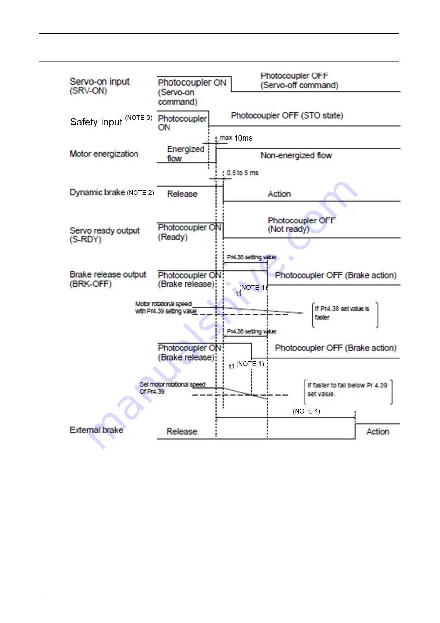
8.5.3.3 Activation to STO state, timing diagram
(NOTE 1)
t1 will be a shorter time of either the setup value of Pr4.38 “Mechanical braking setting during operation” or elapsing
time for the motor speed to fall below Pr4.39 “Brake release speed setup.”
(NOTE 2) Dynamic brake operates to the setting
of Pr5.10 “Sequence at alarm.”
(During STO state, “sequence at alarm” will be applied even though no alarm is generated.)
(NOTE 3) When you use redundant safety input to activate STO function, you should turn safety input OFF at the same time.
(NOTE 4) Since servo-lock cannot be performed in the interval after motor energization is cut off until the external brake
operates, the work may fall by gravity from the vertical axis. Take an appropriate measure to prevent this.
Содержание MINAS A6 Series
Страница 10: ...Table of contents x Blank page...
Страница 11: ...1 Introduction...
Страница 26: ...Introduction 1 16 Blank page...
Страница 27: ...2 Interface Specifications...
Страница 46: ...Interface Specifications 2 20 Blank page...
Страница 47: ...3 Front Panel Specifications...
Страница 48: ...Front Panel Specifications 3 2 3 1 Front panel configuration Front panel cover opened Front panel cover closed...
Страница 57: ...4 Basic Functions...
Страница 85: ...5 Auto Tuning Functions...
Страница 151: ...6 Application Functions...
Страница 185: ...7 Protective Functions...
Страница 224: ...Protective Functions 7 40 Blank page...
Страница 225: ...8 Advanced Safety Functions...
Страница 230: ...Advanced Safety Functions 8 6 When test pulse is used Duplex safety input Safety input...
Страница 245: ...9 List of Parameters...
Страница 281: ...10 Timing Chart...
Страница 290: ...Timing Chart 10 10 Blank page...
Страница 291: ...11 Power Supply Module...


