No. SX-DSV02829 -
93-
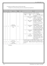
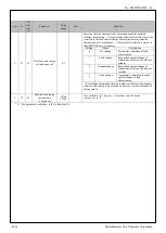
5-2-1 Block diagram of position control mode
Position control of MINAS-A5BL series, there are four modes.
・
Profile position mode
(pp)
・
Cyclic synchronous position mode
(csp)
・
Interpolated position mode (ip) (Not supported)
・
Homing mode (hm)
Velocity
feed forward
Gain
1.10
Filter
1.11
Smoothing
filter
FIR
2.23
Primary
delay
2.22
+
-
Position control
1st
1.00
2nd
1.05
+
+
Damping control
1st
2.14
2nd
2.16
3rd
2.18
2.15
2.17
2.19
4th
2.20
2.21
Switching selection
2.13
Frequency
Filter
+
-
Velocity detection
Friction
compensation
Additional
value
6.07
Positive
direction
6.08
Negative
direction
6.09
Disturbance
observer
Gain
6.23
Filter
6.24
Gain switching
2nd setup
1.14
Mode
1.15
Delay time
1.16
Level
1.17
Hysteresis
1.18
Switching
time
1.19
3rd setup
6.05
Scale factor
6.06
Torque limit
Selection
5.21
Torque feed
forward
Gain
1.12
Filter
1.13
60F4h
Following error
actual value
[command]
+
+
+
+
+
6063h
Position actual
internal value
[pulse]
Velocity detection
filter
1st
1.03
2nd
1.08
Instantaneous
speed
6.10
Notch filter
2.03
2.06
2.09
2.12
Depth
2.02
2.05
2.08
2.11
Width
1st
2.01
2nd
2.04
3rd
2.07
4th
2.10
Frequency
Adaptive mo de
2.00
Velocity control
1.02
1.07
Proportion Integration
Inertia ratio
1st
1.01
2nd
1.06
0.04
6064h
Position actual value
[command]
60BAh
~
60BDh
Touch probe
position value
[command]
Trajectory
generator
606Ch
Velocity actual value
[command/s]
60B1h
Velocity offset
[command/s]
+
+
Velocity FF unit
conversion
60FCh
Position demand
internal value
[pulse]
60B2h
Torque offset
[0.1%]
+
+
MAX
6072
1st
0.13
2nd
5.22
Electronic gear
positive conversion
6062h
Position demand value
(before filter)
[command]
-
+
607Ah
Target position
[command]
Electronic gear
reverse conversion
Positional command
speed [r/min]
command position
CMD_POS
[pulse]
Positional deviation
[pulse]
Velocity control
command
[r/min]
Motor velocity
[r/min]
Internal positional
command speed
[r/min]
Internal command
position (after filter)
MPOS[pulse]
+
+
60B0h
Position offset
[command]
*csp only
Command positional
deviation
*4
[pulse]
Command positional
deviation
*4
[pulse]
Sum of feedback pulses
[pulse]
-
+
6.41
Depth
Torque filter
1st
1.04
2nd
1.09
2 stages
6.42 6.43
At tenuation
term
Main power
supply
Current control
Current
response
9.12
Proportion
9.13
Carrier
selection
9.11
Integration
9.14
Magnetic pole
detected
9.20
CS phase
9.21
Pole position
estimation
relationship
9.22–9.28
CS signal
エンコーダ
feedback
scale
Input setting
Type
3.23
Reversed
3.26
Z phase
invalid
3.27
Scale specification
Resolution
9.01
Maximum
speed
9.10
Moter
Motor specification
Magnetic
pole pitch
9.02
Number of
pole pairs
9.03
Type
selection
9.00
Weight
9.04
Rated
thrust
9.05
Rated
current
9.06
Maximum
current
9.07
Maximum
speed
9.10
Phase
inductance
9.08
Phase
resistance
9.09
6074h
Torque demand
[0.1
%
]
Torque command
TRQ
[0.1%]
Velocity unit
conversion
Block diagram of position control
*1) A slanting number (Example
:
6072h
) shows the object number of EtherCAT.
*2) A bold letter number(Example
:
1.01
) shows a parameter number.
*3) Polarity was omitted.
*4) The calculation method for positional deviation on PANATERM (reference) varies depending on the setting of
command position deviation output switching (bit 14) of 3723h (Communication function Extended setup 2).
Data of CiA402 object
Data of Analog Monitor and Panaterm
R1.00
Motor Business Unit, Panasonic Corporation

