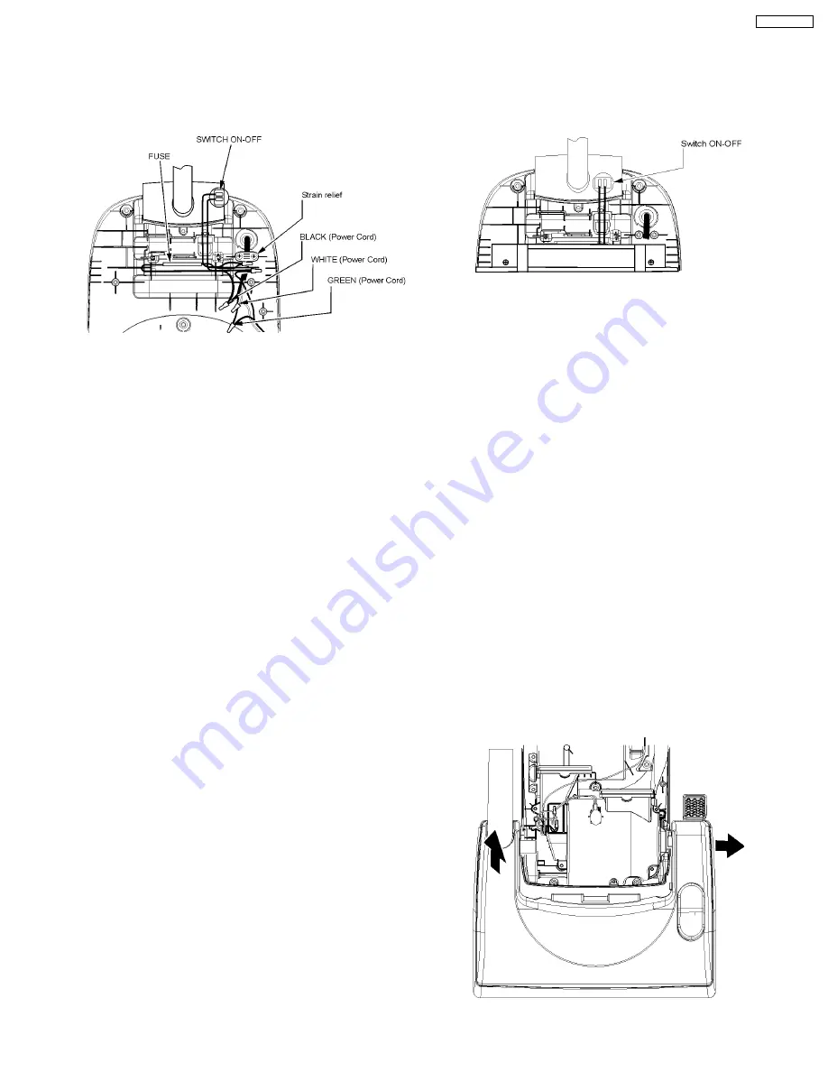
3.5. Power Cord Replacement
3.5.1. Removal
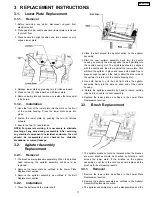
1. Remove the switch cover and dust cover to expose the
electrical connections of the power cord.
2. Remove the strain relief (for power cord replacement) and
cut the wire connections.
3. Pull the power cord out of the dust compartment (for power
cord replacement).
3.5.2. Installation
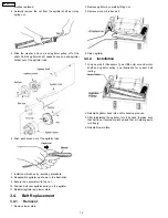
1. Insert the new power cord (power cord replacement only)
into the dust compartment as far as necessary in order to
place a new cord retainer in proper location on power cord.
The proper location is approximately one and one eighth
inches / thirty millimeters (1 1/8” / 30 mm) of new power
cord outer jacket extending past the strain relief. Attach
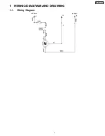
wires with wire connectors according to the wiring diagram
in the front of this manual. ONLY USE A NEW STRAIN
RELIEF, DO NOT REUSE A STRAIN RELIEF.
2. Replace the switch cover, the four (4) switch cover screws,
and the dust cover. Care should be taken not to pinch wires
and make sure that the switch cover goes on easily and
stays flat. If there is resistance to the switch cover lying flat
and in place, stop, remove the cover and make sure that no
wires are being pinched. DO NOT USE A POWER
SCREWDRIVER TO SECURE THE COVER.
NOTE: For general servicing, it is necessary to eliminate
pinching of any wire during reassembly. After servicing
any electrical component or electrical enclosure, the unit
should be reassembled and checked for dielectric
breakdown or current leakage.
3.6. Switch ON-OFF Replacement
3.6.1. Removal
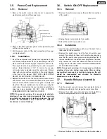
1. Remove the switch cover expose the electrical connections
of the switch.
2. Unplug the lead wire terminals from switch.
3. Pull out the switch from switch cover.
3.6.2. Installation
1. Insert the new switch into the switch cover. Connect the two
lead wires on the new switch.
2. Replace the switch cover, and the four (4) switch cover
screws. Care should be taken not to pinch wires and make
sure that the switch cover goes on easily and stays flat. If
there is resistance to the switch cover lying flat and in place,
stop, remove the cover and make sure that no wires are
being pinched. DO NOT USE A POWER SCREWDRIVER
TO SECURE THE COVER.
NOTE: For general servicing, it is necessary to eliminate
pinching of any wire during reassembly. After servicing
any electrical component or electrical enclosure, the unit
should be reassembled and checked for dielectric
breakdown or current leakage.
3.7. Handle Release Assembly
3.7.1. Removal
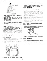
1. Turn the vacuum over and remove the lower plate, belt and
agitator as outlined in their respective removal sections.
2. Remove the switch cover and dust cover to freely lift the
nozzle housing and slide it out from the motor shaft.
3. Remove the three (3) screws that secure the handle release
13
MC-GG773-00


