background image

2

Features

Model

TC-LX60

TC-LX600

Display Capability

480p/720p/1080i

480p/720p/1080i

Aspect Ratio

16:9 (Widescreen)

16:9 (Widescreen)

Aspect Control

Normal, Zoom, Full, and 
Just

Normal, Zoom, Full, and 
Just

Resolution (Number of 
Pixels)

1,049,088 (1366x768) 
pixels

1,049,088 (1366x768) 
pixels

Contrast Ratio

Up to 3000:1

Up to 3000:1

Brightness (Panel, cd/m

2

)

500

500

Integrated ATSC Tuner

Yes

Yes

HDMI-HDCP Interface

1

2

Composite Video Input 

3

3

S-Video Inputs

2

2

Component Video Input

1

1

Monitor Output

1

1

Headphone Jack

Yes

Yes

Содержание Lx-600

Страница 1: ...1 LX600 LCD TV Technical Information Outline Features Overall Block Diagram A Board Main Layout Power On Sequence Protection Shutdown Troubleshooting Adjustments TC 32LX600...

Страница 2: ...ull and Just Normal Zoom Full and Just Resolution Number of Pixels 1 049 088 1366x768 pixels 1 049 088 1366x768 pixels Contrast Ratio Up to 3000 1 Up to 3000 1 Brightness Panel cd m2 500 500 Integrate...

Страница 3: ...Main micro and Video Audio Panel controller IC4004 is a Field Programmable Gate array that is responsible for the pixel conversion and addressing of the Active Matrix display within the LCD Panel Thi...

Страница 4: ...yout Non Serviceable Non Serviceable Non Serviceable This is the board layout of the TC LX600 LCD Television The P board DT board and A board are non serviceable The G board AP board and V board are s...

Страница 5: ...all secondary voltages which include the Main 9V SUB5V Sound 20V Panel 12V Standby 3 3V A Board Comprised of all AV inputs and the HDMI interface with the exception of one AV jack which is located on...

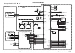
Страница 6: ...6 Board Description...

Страница 7: ...on the G board reside on this board The G board contains an additional AV Jack headphone jack and front panel switches The unit is equipped with a single ATSC tuner which plugs directly onto the A boa...

Страница 8: ...og NTSC and digital ATSC or QAM signal of the DT board are output to the A board via the connector DT12 A12 IC4002 is responsible for processing all video which includes image resizing noise reduction...

Страница 9: ...he HDMI audio bypasses the audio switch and enters IC4002 for selection and processing The output of IC2006 is processed within the Video Audio controller IC4002 The Audio Output from the Video Audio...

Страница 10: ...on the main unit 4 The Sub On signal is issued by IC4002 on pin 8 of connector AP4 This signal is responsible for pulling the contacts on the AC relay on the Power Board 5 The Main_On signal is issue...

Страница 11: ...hed mode power supplies Q7208 serves as a 24V detection line and provides an enable for the Main_ on signal to function if 24V is detected The panel 12V_On signal provides the Enable for the Panel 12V...

Страница 12: ...quency of 125Khz through the use of an internal oscillator and PWM circuit 3 When the switch is closed current flows through coil L7203 causing a field buildup 4 When the switch opens current generate...

Страница 13: ...at a frequency of 125Khz 3 The operation of the 9V supply is similar to that of the 5V supply 4 D7602 is responsible for supplying the 9V to the capacitors when the magnetic field within the coil coll...

Страница 14: ...ss of the 10V 30V Sound 18V and the Panel VCC sources If any of these voltage sources go low it will cause Q7210 to conduct As a result the collector of Q7211 goes low to signal a shutdown condition t...

Страница 15: ...15 AP Board Test Point Locations This page shows the test points that can be accessed to troubleshoot the AP board...

Страница 16: ...16 AP Board LCD Power Distribution Connector AP1 provides the switched 24V from the power unit to the LCD Panel via connectors AP5 and AP7 The 24V can be monitored on connector AP5 or on jumper JS7455...

Страница 17: ...seconds Adjustment method Use the remote control 1 button Main items Selection in forward direction 2 button Main items Selection in reverse direction 3 button Sub items Selection in forward directio...

Страница 18: ...el RF video component Video level RF video component Video level RF video component Tint Adjustment Sub Color Sub Tint Sub Back Light Sub Bright B Y Gain R Y Demodulation axis WHITE 100 Not ADJ RED 10...

Страница 19: ...LUME DOWN button on the front of the unit and the SLEEP button on the remote control Hold the buttons down for at least three seconds The unit self tunes to channel 3 The word SELF CHECK followed by a...

Страница 20: ...ons on Slide 13 Check the cathodes of D7601 D7602 on the AP Board Cathode of D7601 should measure 30V Replace defective component Replace Tuner Check and see if the Tuner Activity indicator is on RED...

Страница 21: ...heck for the BT 30V SUB 9V SUB5V voltages on connector AP3 of the AP board Refer to the AP Board test point locations on Slide 13 Check the video input connections and termination points for a possibl...

Страница 22: ...e it sits on the A board in order to access the LVDS connector There are four screws that need to be removed Check for LVDS activity on Pins 6 8 12 14 16 orange wires of connector A2 on the A board Re...

Страница 23: ...he vicinity of the audio connection in question Are other Audio inputs OK Check the L R speaker output connection Reseat connector A7 Yes Try using a different audio input source Try the Tuner Compone...

Страница 24: ...sent Change the A Board Check for broken connector A7 located on the A board Yes No Check for 20V on pins 2 3 of connector AP3 A3 or jumper J116 Is the Voltage 20V Check regulator IC7218 on the AP Boa...

Страница 25: ...t locations Refer to AP Board test point locations Slide 13 Slide 13 Check for 6V on pin 11 of connector AP2 RELAY Check for STBY 7V on pin 12 of connector AP2 7V Present Yes 6V Present Check for the...

Страница 26: ...fer to the AP Board test point locations Slide 13 Slide 13 Problem solved From Last Page Make sure connector A4 of the A board is seated properly Unit will exhibit this condition if the connector is u...

Страница 27: ...CTP pin 105 8 AP A SOURCE VOLTAGE ABNORMALITY VCTP pin 105 7 AP 9V down VCTP pin 1 6 A P 24V down VCTP pin 106 5 P Panel INVERTER SOS NO BACKLIGHT DETECTION FPGA pin 6 2 SUSPECTED BOARD POSSIBLE CIRCU...

Страница 28: ...ct a voltage check on the AP Board Sound 20V OK No Check and replace if necessary IC7218 and biasing components Main 9V OK 5V OK No Check and replace if necessary IC7210 and biasing components Check a...

Страница 29: ...for 24V on jumper JS7455 or on connector AP5 pins 1 8 24V OK No 24V OK No Unplug connector AP5 and measure for 24V on jumper JS7455 or on connector AP5 pins 1 8 Change the P board Yes END Confirm that...

Страница 30: ...30 Examples of Defective Panels Green Red or Blue Shading Horizontal Lines Distorted Partial Picture...

Страница 31: ...31 Pedestal Removal...

Страница 32: ...32 Pedestal Removal...

Страница 33: ...33 The End The End...

Отзывы: