background image

3

1 Safety Precautions

1.1.

General Guidelines

1.

IMPORTANT SAFETY NOTICE

There are special components used in this equipment 
which are important for safety. These parts are marked by         

 in the Schematic Diagrams, Circuit Board Layout, 

Exploded Views and Replacement Parts List. It is 
essential that these critical parts should be replaced with 
manufacturer’s specified parts to prevent X-RADIATION, 
shock, fire, or other hazards. Do not modify the original 
design without permission of manufacturer.

2. An Isolation Transformer should always be used during 

the servicing of AC Adaptor whose chassis is not isolated 
from the AC power line. Use a transformer of adequate 
power rating as this protects the technician from 
accidents resulting in personal injury from electrical 
shocks. It will also protect AC Adaptor from being 
damaged by accidental shorting that may occur during 
servicing.

3. When servicing, observe the original lead dress. If a short 

circuit is found, replace all parts which have been 
overheated or damaged by the short circuit.

4. After servicing, see to it that all the protective devices 

such as insulation barriers, insulation papers shields are 
properly installed.

5. After servicing, make the following leakage current 

checks to prevent the customer from being exposed to 
shock hazards.

1.2.

Leakage Current Cold Check

1. Unplug the AC cord and connect a jumper between the 

two prongs on the plug.

2. Measure the resistance value, with an ohmmeter, 

between the jumpered AC plug and each exposed 
metallic cabinet part on the equipment such as 
screwheads, connectors, control shafts, etc. When the 
exposed metallic part has a return path to the chassis, the 
reading should be between 1 M

 and 5.2 M

. When the 

exposed metal does not have a return path to the chassis, 
the reading must be infinity.

1.3.

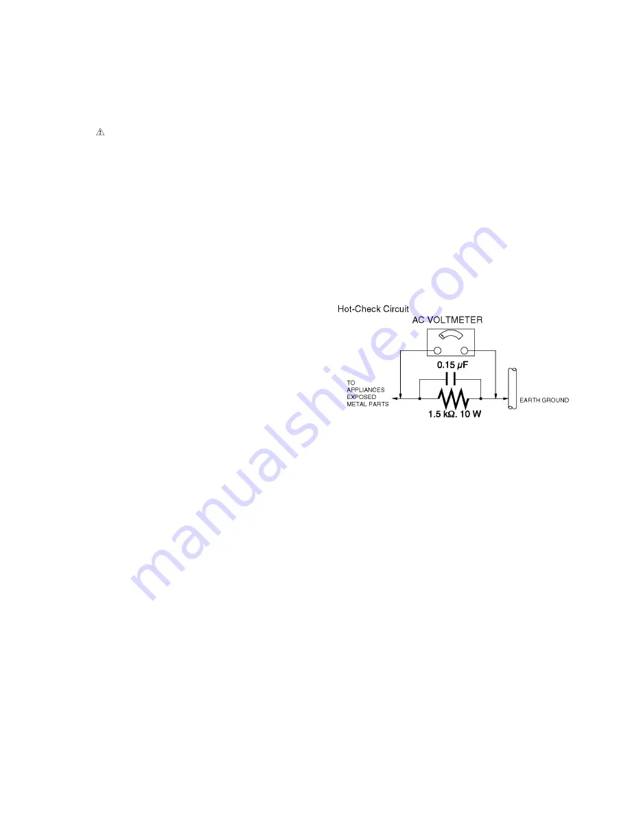
Leakage Current Hot Check 
(See Figure 1.)

1. Plug the AC cord directly into the AC outlet. Do not use 

an isolation transformer for this check.

2. Connect a 1.5 k

, 10 W resistor, in parallel with a 0.15 

µ

capacitor, between each exposed metallic part on the set 
and a good earth ground, as shown in Figure 1.

3. Use an AC voltmeter, with 1 k

/V or more sensitivity, to 

measure the potential across the resistor.

4. Check each exposed metallic part, and measure the 

voltage at each point.

5. Reverse the AC plug in the AC outlet and repeat each of 

the above measurements.

6. The potential at any point should not exceed 0.75 V RMS. 

A leakage current tester (Simpson Model 229 or 
equivalent) may be used to make the hot checks, leakage 
current must not exceed 1/2 mA. In case a measurement 
is outside of the limits specified, there is a possibility of a 
shock hazard, and the equipment should be repaired and 
rechecked before it is returned to the customer.

Figure. 1

Содержание Lumix DMC-LZ30P

Страница 1: ...ng and distribution is a violation of law ORDER NO DSC1303009CE B26 Digital Camera Model No DMC LZ30P DMC LZ30PC DMC LZ30PU DMC LZ30E DMC LZ30EE DMC LZ30GC DMC LZ30GF DMC LZ30GW DMC LZ30GK DMC LZ30GN...

Страница 2: ...w to Define the Model Suffix NTSC or PAL model 7 4 Specifications 9 5 Location of Controls and Components 10 6 Service Fixture Tools 12 6 1 Service Fixture and Tools 12 7 Disassembly and Assembly Inst...

Страница 3: ...posed to shock hazards 1 2 Leakage Current Cold Check 1 Unplug the AC cord and connect a jumper between the two prongs on the plug 2 Measure the resistance value with an ohmmeter between the jumpered...

Страница 4: ...rging Procedure 1 Refer to the disassemble procedure and remove the necessary parts unit 2 Install the insulation tube onto the lead part of resistor ERG5SJ102 1k 5W an equivalent type of resistor may...

Страница 5: ...solder ES devices 4 Use only an antistatic solder removal device Some solder removal devices not classified as antistatic ESD protected can generate electrical charge sufficient to damage ES devices 5...

Страница 6: ...pair work using Lead Free Solder PbF The lead free solder has to be used when repairing the equipment for which the lead free solder is used Definition The letter of PbF is printed on the P C B using...

Страница 7: ...C GF GW What is the difference is that the Initial Setting data which is stored in Flash ROM mounted on MAIN P C B 3 4 1 Defining methods To define the model suffix to be serviced refer to the namepla...

Страница 8: ...ool 2 Connect the DSC to PC by USB cable 1 Set the battery to the camera 2 Turn off the power 3 Press Tele Menu Set Playback key at the same time It starts in the state of Engineer Mode automatically...

Страница 9: ...9 4 Specifications NOTE The following specification is for DMC LZ30 Some specifications may differ depending on model suffix...

Страница 10: ...10 5 Location of Controls and Components NOTE The following description is for DMC LZ30 Some descriptions may differ depending on model suffix...

Страница 11: ...11...

Страница 12: ...12 6 Service Fixture Tools 6 1 Service Fixture and Tools The following Service Fixture and tools are used for checking and servicing this unit REMARKS 1 ABOUT LIGHT BOX...

Страница 13: ...13 7 Disassembly and Assembly Instructions 7 1 Disassembly Flow Chart This is a disassembling chart When installing perform this chart conversely 7 2 PCB Location...

Страница 14: ...9 6 Screws G Frame Plate Tripod 4 Top Case Unit Fig D10 Connector B Top Case Unit 5 Battery Door Unit Fig D11 Battery Door Shaft Battery Door Unit 6 Main P C B Fig D12 3 Screws H FPC Sheet Fig D13 Con...

Страница 15: ...15 Fig D3 Fig D4 Fig D5 Fig D6...

Страница 16: ...16 Fig D7 7 3 2 Removal of the LCD Unit Fig D8 7 3 3 Removal of the Frame Plate Fig D9 7 3 4 Removal of the Top Case Unit Fig D10...

Страница 17: ...17 7 3 5 Battery Door Unit Fig D11 7 3 6 Removal of the Main P C B Fig D12...

Страница 18: ...18 Fig D13...

Страница 19: ...or the Lens Unit 1 Take care that the dust and dirt are not entered into the lens In case of the dust is putted on the lens blow off them by airbrush 2 Do not touch the surface of lens 3 Use lens clea...

Страница 20: ...stalling Make sure to confirm the following points when installing The Screw is tightened enough Installing conditions are fine No distortion no abnormal space No dust and or dirt on Lens surfaces LCD...

Страница 21: ...bling the lens in order to maintain it clean 2 Keep dust or dirt away from the Lens 3 To remove dirt or dust from the Lens blow with dry air 4 Do not touch the Lens surface 5 Use Lens cleaning KIT BK...

Страница 22: ...at TSN Website 8 2 Matrix chart Replaced part and Adjustment item The following matrix table shows the relation between the replaced part and the necessary adjustment When a part is replaced make sure...

Страница 23: ...2 Connect the DSC to PC by USB cable 1 Set the battery to the camera 2 Turn off the power 3 Press Tele Menu Set Playback key at the same time It starts in the state of Engineer Mode automatically 4 Co...

Страница 24: ...hand is recommended f CARD Check SD card socket can be read write g AUDIO Check MIC and Speaker by REC PLAY audio file Input voice when ADUIO REC is displayed h Memory Check Internal memory size 6 Whe...

Страница 25: ...Setting the DSC 1 Set the battery to the camera 2 Turn off the power 3 Press Tele Menu Set Playback key at the same time It starts in the state of Engineer Mode automatically 4 Press Playback key to...

Страница 26: ...gain and select OK and press Menu Set Key to start checking 5 When calibration finishes the screen will show the result OK or NG 6 Choose MeShut80 LV14 and operate and execute calibration same as MeSh...

Страница 27: ...ult OK or NG 6 Press PLAYBACK Key to return to calibration menu Carrying out this adjustment after 25 minutes after power ON is recommended It takes several minutes 8 3 10 FLASHWB Calibration 1 Settin...

Страница 28: ...PC by USB cable 1 Set the battery to the camera 2 Turn off the power 3 Press Tele Menu Set Playback key at the same time It starts in the state of Engineer Mode automatically 4 Connect the DSC to PC b...

Страница 29: ...D Panel with your hand When cleaning the lens use air Blower to blow off the dust When cleaning the LCD Panel dampen the lens cleaning paper with lens cleaner and the gently wipe the its surface Note...

Страница 30: ...30...

Страница 31: ...F SD Memory I F TOP KEY FPC POWER Interface CCD UNIT 9 PIN connector J12 39 PIN connector J11 GPADC I F SYS_PLL NAND Battery Thermal Detect Stroge DISPLAY I F STROBE Board Interface GPIO I F ASIC GPIO...
Страница 32: ...OBE CHARGE POWER IC CH6 SET_UP CCD_13V POWER IC CH4 STROBE IC 3 1V REGULATOR M4V9 ASIC_3V3 SD_3V3 PWR_CCD POWER SW POWER HOLD F W PWR_CCD_N POWER IC CH1 EN4 PWR_LCD EN123 4 ALKALINE BATTERY STEP DOWN...

Страница 33: ...AF LED FRAME UNIT STOROBE P C B FRAME UNIT MAIN P C B COMPONENT SIDE MICROPHONE FRAME UNIT LS1 MIC1 AFLED1 CCD UNIT LCD UNIT TP26 TP25 J8 J12 J2 J11 SW P C B FRAME UNIT J9 1 J9 2 SPEAKER FRAME UNIT J...

Отзывы: