Panasonic Lumix DMC-FZ200P Скачать руководство пользователя страница 54

54

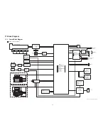
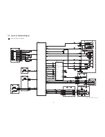
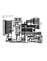
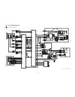
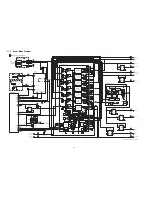
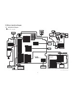
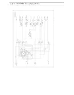
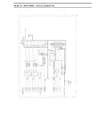
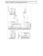
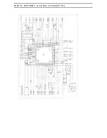
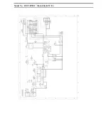
11.3. Video/Audio Process Block Diagram

VIDEO/AUDIO PROCESS BLOCK DIAGRAM

DMC-FZ200  VIDEO/AUDIO PROCESS BLOCK DIAGRAM

+

-

ECM[R]

+

-

ECM[L]

7

8

9

1

2

5

10

12

D0

D1

D2

D3

CMD

CLK

WP

6

(SDCD)

C.DET

IC6001

(VENUS ENGINE)

GPIO29

GPIO27

(S SYSCON SO)

(S SYSYCON SCK)

FP9003

36

FP9003

1

35

FP9003

34

FP9003

15

FP9003

17

6

FP9003

7

FP9003

FP9003

33

18

FP9003

FP9003

16

IS SAB0 P

IS SAB0 M

IS SAB1 P

IS SAB1 M

IS SAB2 P

IS SAB2 M

IS SAB3 P

IS SAB3 M

IS SAB4 P

IS SAB4 M

IS SAB5 P

IS SAB5 M

IS SBCD6 P

IS SBCD6 M

IS SBCD7 P

IS SBCD7 M

IS SB8CCK P

IS SB8CCK M

IS SBCD9 P

IS SBCD9 M

IS0 HD

IS0 VD

IS0 SDO

IS0 SCK

(S MOS CS)

(MOS HD)

(MOS VD)

(BUS288 D0AP)

(BUS288 D0AM)

(BUS288 D0BP)

(BUS288 D0BM)

(BUS288 D0CP)

(BUS288 D0CM)

(BUS288 D0DP)

(BUS288 D0DM)

(BUS288 D0EP)

(BUS288 D0EM)

(BUS288 D01P)

(BUS288 D01M)

(BUS288 D0HP)

(BUS288 D0HM)

(BUS288 D0JP)

(BUS288 D0JM)

(BUS288 D0GP)

(BUS288 D0GM)

(BUS288 D0FP)

(BUS288 D0FM)

(S MOS SDO)

(S MOS SCK)

IS0 CS

LCDOUT0

LCDOUT15

(LCDOUT0-15)

(LCDOUT0-15)

AF15

AD16

GPIO45

GPIO47

(S I2C SCL)

(S I2C SDA)

AB18

AB16

D15

M26

M24

M23

N23

P26

P25

P24

P23

R24

R23

J24

J25

K24

T26

T25

T24

T23

U26

U25

U24

U23

K25

J26

N24

M25

A19

GPIO48 AB15

MOS

IMAGE

SENSOR

12M

CL9031

CL9030

IS RESET

(MOS RESET)

L24

AD2 IN3

AD2 IN2

C12

AA26

AB24

AB23

AB26

D12

AB25

AA25

LCD BACK LIGHT

SDRAM AREA/2G-bit

FP9001

38

FP9001

39

FP9001

36

FP9001

37

FP9001

30

FP9001

31

FP9001

18

FP9001

19

FP9001

20

FP9001

21

FP9001

22

FP9001

23

FP9001

24

FP9001

25

FP9001

26

FP9001

27

IS SBCK P

IS SBCK M

(BUS288 DCKP)

(BUS288 DCKM)

R26

R25

FP9001

28

FP9001

29

(MOS THERMO)

AD0 IN2

C11

FP9001

51

FP9001

45

FP9001

46

FP9001

43

FP9001

44

FP9001

42

FP9001

50

FP9001

34

FP9001

35

FP9001

32

FP9001

33

MOS
SSG

RL9002

LCDCLK

(CLK27 LCD)

(LCD CS)

(LCD VD)

(LCD HD)

(LCD CLK)

(LCD CS)

(LCD SDOUT)

(LCD SCK)

(LCDVD)

(LCDHD)

A20

C20

B20

LCDVD

LCDHD

EVF

FP9004

27

12

FP9004

3

FP9004

FP9004

29

28

FP9004

PW BL PLUS

PW BL MINUS

RL9003

RL9004

LCD

11

(SDWP)

(SDCD SYS)

2

3

USB+

5

USB-

7

8

4

6

CL5003

CL5002

CL5001

CL5007

85

89

VIDEO OUT

IC9101

(SYSTEM IC)

IC5001

(BUS SWITCH)

LRCLK

RSTB

96

2

12

10

4

1

76

SPPOS

79

SPNEG

CABLE DET

1

(CABLE DET)

(EXT MIC ON H)

(AV KEY DET)

GPIO43

GPIO50

GPIO24

AUD DIN

AUD DOUT

AUD FCLK

CL2001

CL2005

CL2007

CL2006

CL2002

CL2003

CL5201

CL5207

CL5011

CL5017

CL9057

RL5102

RL9302

RL9301

RL5101

RL5104

RL5103

CL9051

(G VIDEO OUT)

(SYS RESET)

V IN

(USB CAB IN)

51

5

6

82

CL9101

CL5006

92

JK2001
(AV OUT/DIGITAL TERMINAL)

LINE OUT

VIDEO OUT

USB CAB IN

A8

AB13

AD0 IN3 D11

USBSIGDM

AE8

AC12

63

(G USB-)

(A DIN)

(A FCLK)

SDDETOUT

SDDETIN

RL9112

RL5003

RL5002

4

3

(A DOUT)

RL5001

ADOUT

DAIN

AE10

4

AUD MCLK

AUD DCLK

AE9

(A MCLK)

RL5004

4

17

(A DCLK)

RL5005

14 MCLKO

BCLK

AF9

AF8

RESET OUT

LINEOUTL

MUTEL

MICINL

99

MICINR

100

MREG

1A(L)

2A(R)

S

2B1

1B1

11

1B2

9

2B2

EXT  MIC/
REMOTE

MIC

POWER

SW

Q5201,5206
QR5201,5202

FP9006

27

FP9302

8

FP9006

28

FP9302

9

FP9006

30

FP9302

11

JK9301

M5001

M5002

71 SCSI

70 SCSCLK

E1

2

3

4

1

L2001

CL9033

FP9010

3

FP9010

1

ECM FPC

(Built in AFE)

(SDDAT0)

(SDDAT1)

(SDDAT2)

(SDDAT3)

(SDCMD)

(SDCLK)

GPIO88

GPIO89

FR RB

CPUREB

FROM CS

FR CLE

FR ALE

CPUWE2B

FR WP

F26 F25

GPIO90

GPIO91

E26 E25

GPIO84

GPIO85

H25 H24

GPIO86

GPIO87

G26 G25

D26 E24

J23

H23 D25 F24

G24

DATA

44

41

32

29

IC6005

(NAND FLASH ROM/1G-bit) 

7

8 9 16 17 18 19

CTL SIG

D2+

2

D2-

3

D1+

5

D1-

6

D0+

8

D0-

9

CK+

11

CK-

12

CEC

14

SCL

15

SDA

16

19

1

5

6

2

3

7

8

4

1

5

6

2

3

7

8

4

JK2002
(HDMI TERMINAL)

HDMI TXCM

HDMI SDA

HDMI HPD

HDMI SCL

HDMI CEC AD8

AE7
AF7

AD9

K1

HDMI TX0P

HDMI TX2P

HDMI TX2M

HDMI TX1P

HDMI TX1M

N1

M1

L1

FL2001

FL2002

HPDTCT

HDMI TX0M

HDMI TXCP

P1

(G HDMI D2+)

(G HDMI D2-)

(G HDMI D1+)

(G HDMI D1-)

(G HDMI D0+)
(G HDMI D0-)

(G HDMI CK+)

(G HDMI CK-)
(HDMI CEC)

(S HDMI SCL)

(S HDMI SDA)

(HDMI HPDTCT)

T1

U1

R1

AB20

USBSIGDP D1

(G USB+)

61

V OUT

(G SDTV OUT)

(G LINE OUT)

SD DAT0

SD DAT1

SD DAT2

SD DAT3

SD CMD
SD CLK

(G EX MIC L)

(G EX MIC LIN)

(G EX MIC RIN)

(G MIC LIN)

(G MIC RIN)

(G EX MIC R)

(REMOTE)

PW HDMI5.0V

LCD IF P.C.B.

DR0-7/DG0-7

VSYNC

HSYNC

DCLK

SCEN

SDA

SCL

AC17

RL9102

RL9103

(CLOCK)

(VSYNC)

(HSYNC)

30

FP9004

FP9004

31

FP9004

7-9

(SCL)

(SDA)

(VCC LED)

(DATA0-15)

MEMORY CONTROL BLOCK

YC
PROCESS
BLOCK

JPEG
PROCESS
BLOCK

VIDEO
OUTPUT
BLOCK

SD CORE

USB I/F

PRE
PROCESS
BLOCK

INTERNAL BUS CONTROL

SUB P.C.B.

(G SP POS)

(G SP NEG)

SPEAKER

6

FP9302

7

FP9302

24

FP9006

25,26

FP9006

QR6001

GPIO17

(EVF 3V CTL)

AF18

MCK24I

(CLK72 MCLK)

H1

FP9001

48

5

1

4

3

2

IC6004

(AND GATE IC)

X6081

(72MHz)

PW D3.0V

PW D3.0V

P6401
(SD CARD CONNECTOR)

QR9003

1

2

6

4

5

3

PW AF3.4V

Содержание Lumix DMC-FZ200P

Страница 1: ...tribution is a violation of law ORDER NO DSC1208028CE B26 Digital Camera Model No DMC FZ200P DMC FZ200PC DMC FZ200PU DMC FZ200EB DMC FZ200EE DMC FZ200EF DMC FZ200EG DMC FZ200EP DMC FZ200GC DMC FZ200GK...

Страница 2: ...ls and Components 16 6 Service Mode 17 6 1 Error Code Memory Function 17 7 Service Fixture Tools 20 7 1 Service Fixture and Tools 20 7 2 When Replacing the Main P C B 21 7 3 Service Position 21 8 Disa...

Страница 3: ...g exposed to shock hazards 1 2 Leakage Current Cold Check 1 Unplug the AC cord and connect a jumper between the two prongs on the plug 2 Measure the resistance value with an ohmmeter between the jumpe...

Страница 4: ...ocedure 1 Refer to the disassemble procedure and remove the necessary parts unit 2 Install the insulation tube onto the lead part of resistor ERG5SJ102 1k 5W An equivalent type of resistor may be used...

Страница 5: ...ces 4 Use only an antistatic solder removal device Some solder removal devices not classified as antistatic ESD protected can generate electrical charge sufficient to damage ES devices 5 Do not use fr...

Страница 6: ...ust not be used until a replacement cover is obtained A replacement fuse cover can be purchased from your local Panasonic Dealer If the fitted moulded plug is unsuitable for the socket outlet in your...

Страница 7: ...subjected to excessive heat or discharge It must therefore only be fitted in requirement designed specifically for its use Replacement batteries must be of same type and manufacture They must be fitte...

Страница 8: ...MOS unit fixing screws are loosened the Optical tilt adjustment must be performed About the Optical tilt adjustment refer to the 9 3 2 Adjustment Specifications for details NOTE It is necessary to use...

Страница 9: ...for which the lead free solder is used Definition The letter of PbF is printed on the P C B using the lead free solder To put lead free solder it should be well molten and mixed with the original lea...

Страница 10: ...f DMC FZ200GK g DMC FZ200GN h DMC FZ200GC PU What is the difference is that the INITIAL SETTINGS data which is stored in Flash ROM mounted on MAIN P C B 3 4 1 Defining methods To define the model suff...

Страница 11: ...he lens cap Step 1 The temporary cancellation of INITIAL SETTINGS Set the mode dial to P Program AE mode While pressing UP of Cursor button and MOTION PICTURE button simultaneously turn the Power on S...

Страница 12: ...just been replaced only 7 model suffix are displayed as follows Two pages in total CASE 2 Other than After replacing MAIN P C B Step 5 Choose the model suffix in INITIAL SETTINGS Refer to CAUTION 1 Ca...

Страница 13: ...ndition is as shown in the following table Default setting After INITIAL SETTINGS MODEL VIDEO OUTPUT LANGUAGE DATE REMARKS a DMC FZ200 Japan domestic model NTSC Japanese Year Month Date b DMC FZ200P N...

Страница 14: ...14 4 Specifications The following specification is for DMC FZ200P DMC FZ60P Some specifications may differ depending on model suffix...

Страница 15: ...15...

Страница 16: ...button 20 Rear dial 21 DISP button 22 MENU SET button 23 Cursor buttons 24 Q MENU button Delete Cancel button 25 Playback button 26 EVF LCD button 27 LCD monitor 28 Tripod mount A tripod with a screw...

Страница 17: ...can be displayed by ordering the following procedure Preparation Attach the Battery or AC Adaptor with a DC coupler to the unit Since this unit has built in memory it can be performed without insertin...

Страница 18: ...18 3 Error Code List The error code consists of 8 bits data and it shows the following information...

Страница 19: ...this error occurred under the condition of INITIAL SETTINGS has been released Example Factory assembling line before unit shipment Service mode etc It means that this error is occurred at service sid...

Страница 20: ...20 7 Service Fixture Tools 7 1 Service Fixture and Tools The following Service Fixture and tools are used for checking and servicing this unit...

Страница 21: ...e S1 Extension Cable List CAUTION 1 When servicing FLASH P C B 1 Be sure to discharge the E Capacitor on FLASH P C B Refer to HOW TO DISCHARGE THE E CAPACITOR ON FLASH P C B The E Capacitor voltage is...

Страница 22: ...22 8 Disassembly and Assembly Instructions 8 1 Disassembly Flow Chart This is a disassembling chart When assembling perform this chart conversely 8 2 P C B Location...

Страница 23: ...R Strap Holder R 1 Screw J 2 Locking tabs Front Heat Sink 3 Screws K Fig D12 Lens Ring Front 2 Convexes Side Switch Unit 10 Flash P C B Fig D13 3 Locking tabs Condensor Cover Fig D14 2 Screws L 2 Loc...

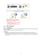
Страница 24: ...24 8 3 1 Removal of the Rear Case Unit Fig D1 Fig D2...

Страница 25: ...25 8 3 2 Removal of the Rear Operation Unit Fig D3 8 3 3 Removal of the Main P C B Fig D4...

Страница 26: ...26 8 3 4 Removal of the Top Operation Unit Fig D5 8 3 5 Removal of the Battery Case Unit Fig D6 Fig D7...

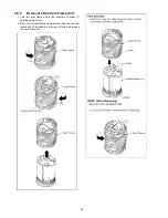
Страница 27: ...27 8 3 6 Removal of the Lens Unit W MOS Fig D8 8 3 7 Removal of the EVF Unit Flash Parts Fig D9...

Страница 28: ...28 8 3 8 Removal of the Sub P C B and Speaker Fig D10 8 3 9 Removal of the Side Switch Unit Fig D11...

Страница 29: ...29 Fig D12 8 3 10 Removal of the Flash P C B Fig D13...

Страница 30: ...30 Fig D14 8 3 11 Removal of the EVF Unit Fig D15 8 3 12 Removal of the Hot Shoe Unit Flash and Mic FPC Unit Fig D16...

Страница 31: ...31 Fig D17 Fig D18...

Страница 32: ...32 Fig D19 Fig D20...

Страница 33: ...33 8 3 13 Removal of the LCD Parts and Hinge SW FPC Fig D21 Fig D22...

Страница 34: ...en Installing Make sure to confirm the following points when installing The screw is tightened enough Installing conditions are fine No distortion no abnormal space No dust and or dirt on Lens surface...

Страница 35: ...axis adjust ment finished When remove it refer to item 8 5 2 Keep dust or dirt away from the lens To remove dirt or dust from the lens blow with dry air 3 Do not touch the lens surface 4 Use lens clea...

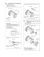
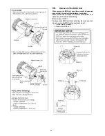
Страница 36: ...36 8 4 3 Removal of the Zoom Motor 1 Unscrew the 2 screws C...

Страница 37: ...37 8 4 4 Removal of the 1st Lens Frame Unit 1 Turn the cam frame in the direction of arrow fully and remove the 1st lens frame unit...

Страница 38: ...38 8 4 5 Removal of the 5th Lens Frame Unit 1 Remove the 5th lens frame unit in the direction of arrow...

Страница 39: ...the 2nd Lens Frame Unit 1 Hold the middle frame unit and turn the cam frame unit in the direction of arrow 1 fully about half turn 2 Reverse the cam frame and remove the 2nd lens frame unit Catch the...

Страница 40: ...Cam Frame Unit 1 Turn the cam frame unit in the direction of arrow 1 fully about half turn 2 Move the 3rd lens frame unit to bottom And turn the cam frame unit in the direction of arrow 2 fully and re...

Страница 41: ...Motor Unit 1 Unscrew the 2 screws D 2 Remove the focus motor unit Also remove the flex from groove 8 4 9 Removal of the 4th and 3rd Lens Frame Unit 1 Remove the 4th lens frame unit and 3rd lens frame...

Страница 42: ...the optical tilt adjustment is required When loosen the screw E the optical tilt adjustment is necessary at the end of assembling Refer to item 9 3 2 To prevent the MOS unit from catching the dust and...

Страница 43: ...43...

Страница 44: ...t software in the camera is not able to be executed when the align ment is carried out Note The initial setting should be again done after completing the alignment Otherwise the camera may not work pr...

Страница 45: ...into the camera 2 Set the camera to Temporary cancellation of the initial settings 3 Select the SETUP menu From the SETUP menu select ROM BACKUP NOTE This item is not listed on the customer s SETUP me...

Страница 46: ...MODE Refer to Fig 3 1 9 3 1 2 Status Adjustment Flag Setting Reset Not yet adjusted the status flag condition 1 After pressing the DISPLAY button the LCD monitor displays the Flag status screen Refer...

Страница 47: ...g If one of these is moved accidentally start the adjustment again 3 Do not press any buttons keys until the default menu Fig 3 5 is displayed on the LCD monitor Otherwise adjustment data may not be s...

Страница 48: ...table shows the relation between the replaced part and the Necessary Adjustment When a part is replaced make sure to perform the necessary adjustment s in the order indicated The table below shows al...

Страница 49: ...49...

Страница 50: ...scribed in 3 4 2 INITIAL SETTINGS for details IMPORTANT 1 The initial setting should be done again after completing the alignment Otherwise the camera will not work properly Therefore as a warning the...

Страница 51: ...inder and LCD Panel with your hand When cleaning the lens use air Blower to blow off the dust When cleaning the LCD Panel dampen the lens cleaning paper with lens cleaner and the gently wipe the its s...

Страница 52: ...SYSTEM IC ZOOM OIS CONTROL LENS DRIVE LCD DRIVE SDRAM 2G bit HDMI DRIVE AV OUT DIGITAL TERMINAL IC7101 GYRO SENSOR IC9101 SYSTEM IC MICROPHONE AMP SPEAKER CONTROL SPEAKER VIDEO OUT IC1021 1041 1043 IC...

Страница 53: ...0 GPIO30 GPIO28 GPIO29 GPIO27 RSTB B9 GPIO72 GPIO73 GPIO71 Y4 11 LEDOUT1 AF LED K AF LED K 8 LEDOUT2 D8011 AF ASSIST LED AA1 Y3 SW7301 SW7401 LCD ROTATE2 LCD ROTATE1 MODE DIAL FP9002 10 FP9002 4 11 FP...

Страница 54: ...DET GPIO43 GPIO50 GPIO24 AUD DIN AUD DOUT AUD FCLK CL2001 CL2005 CL2007 CL2006 CL2002 CL2003 CL5201 CL5207 CL5011 CL5017 CL9057 RL5102 RL9302 RL9301 RL5101 RL5104 RL5103 CL9051 G VIDEO OUT SYS RESET V...

Страница 55: ...22 Y26 Y25 AC21 AF20 Y24 ZOOM ENC LZCK LZDI LZLD EC1 EB EA RL7005 STB CHG OUT 12 PIOUT2 9 PIOUT1 118 MRIN1 119 MRIN2 MROUT1 MROUT2 44 ED2 RL7006 AE21 GPIO7 2 PWM IRIS B RL7002 EC2 AD21 AE19 AD19 AF21...

Страница 56: ...To FP9003 6 CL9011 CL9012 CL1010 PW 5 2V CL1050 CL1020 CL1030 CL1040 CL1021 PW A3 1V IC1041 REGULATOR 3 2 1 4 VDD VOUT CNT GND CL1041 CL1080 SERIAL I F Vo3SEL SERIAL I F SERIAL I F SERIAL I F SERIAL...

Страница 57: ...ZM1 DCM ZM2 DCM ZM2 DCM ENC VCC D2R9V ABS ZENC2 LED CONT Z2 LED FAN FMAN FBP FMBP FAP FMAP FBN FMBN FHP VCC D2R9V ABS FHP LED CONT FHP LED ST2 IRIS AN ST1 IRIS AP ST4 IRIS BN ST3 IRIS BP Y DRV Y DR Y...

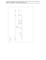
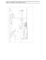
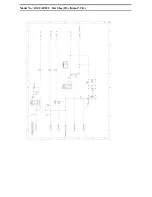
Страница 58: ...Model No DMC FZ200 Schematic Diagram Note...

Страница 59: ...Model No DMC FZ200 Parts List Note...

Страница 60: ...Model No DMC FZ200 Power P Main P C B...

Страница 61: ...Model No DMC FZ200 Jack J Main P C B...

Страница 62: ...Model No DMC FZ200 EXT MIC EM Main P C B...

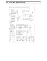
Страница 63: ...Model No DMC FZ200 Digital D Main P C B...

Страница 64: ...Model No DMC FZ200 SD Card SD Main P C B...

Страница 65: ...Model No DMC FZ200 Gyro GY Main P C B...

Страница 66: ...Model No DMC FZ200 Hot Shoe HS Main P C B...

Страница 67: ...Model No DMC FZ200 Main Connection MC Main P C B...

Страница 68: ...Model No DMC FZ200 System Driver SY Main P C B...

Страница 69: ...Model No DMC FZ200 Flash Flash P C B...

Страница 70: ...Model No DMC FZ200 Sub Sub P C B...

Страница 71: ...Model No DMC FZ200 Lens Flex Lens Flex P C B...

Страница 72: ...Model No DMC FZ200 Main P C B Component Side...

Страница 73: ...Model No DMC FZ200 Main P C B Foil Side...

Страница 74: ...Model No DMC FZ200 Flash P C B Component Side...

Страница 75: ...Model No DMC FZ200 Flash P C B Foil Side...

Страница 76: ...Model No DMC FZ200 Sub P C B Component Side...

Страница 77: ...Model No DMC FZ200 Sub P C B Foil Side...

Страница 78: ...Model No DMC FZ200 Lens Flex P C B...

Страница 79: ...1 C1060 F1J1A106A043 C CAPACITOR CH 10V 10U 1 C1061 ECJ1VB1A105K C CAPACITOR CH 10V 1U 1 C1062 ECJ1VB1A105K C CAPACITOR CH 10V 1U 1 C1070 F1J1V1050001 C CAPACITOR CH 35V 1U 1 C1091 F1G0J1050007 C CAP...

Страница 80: ...10V 0 1U 1 C6053 F1G1C1030008 C CAPACITOR CH 16V 0 01U 1 C6081 F1G1A1040006 C CAPACITOR CH 10V 0 1U 1 C6084 F1G1A1040006 C CAPACITOR CH 10V 0 1U 1 C6085 F1G1C1030008 C CAPACITOR CH 16V 0 01U 1 C6086 F...

Страница 81: ...1 C9111 F1J1A106A043 C CAPACITOR CH 10V 10U 1 C9112 F1G1A1040006 C CAPACITOR CH 10V 0 1U 1 CX6001 F5A84103A020 CAPACITOR NETWORKS 1 CX6002 F5A84103A020 CAPACITOR NETWORKS 1 CX6003 F5A84103A020 CAPACIT...

Страница 82: ...000107 FILTER 1 LB2007 J0JBC0000107 FILTER 1 LB2008 J0JBC0000107 FILTER 1 LB6002 J0JYC0000046 FILTER 1 LB6004 D0YAR0000007 FILTER 1 LB9001 J0JCC0000415 FILTER 1 LB9002 J0JCC0000415 FILTER 1 LB9003 J0J...

Страница 83: ...STOR CH 1 10W 4 7K 1 R6009 ERJ2GEJ102Y M RESISTOR CH 1 10W 1K 1 R6012 ERJ2RHD511 M RESISTOR CH 1 16W 510 1 R6013 ERJ2GEJ101 M RESISTOR CH 1 10W 100 1 R6022 ERJ2RKF6201 M RESISTOR CH 1 16W 6 2K 1 R6026...

Страница 84: ...2GEJ102Y M RESISTOR CH 1 10W 1K 1 R9024 ERJ2GEJ101 M RESISTOR CH 1 10W 100 1 R9026 ERJ2GEJ101 M RESISTOR CH 1 10W 100 1 R9033 ERJ2GEJ101 M RESISTOR CH 1 10W 100 1 R9041 ERJ2RKF1000 M RESISTOR CH 1 16W...

Страница 85: ...BN8V103J RESISTOR NETWORKS 1 RX6051 EXBN8V101JX RESISTOR NETWORKS 1 RX6052 EXBN8V101JX RESISTOR NETWORKS 1 RX6053 EXBN8V101JX RESISTOR NETWORKS 1 RX6054 EXBN8V101JX RESISTOR NETWORKS 1 RX6401 EXBN8V47...

Страница 86: ...Model No DMC FZ200 Frame and Casing Section...

Страница 87: ...Model No DMC FZ200 Camera Lens Section...

Страница 88: ...Model No DMC FZ200 Packing Parts and Accessories Section...

Страница 89: ...A FLASH P C B 1 PAVCX RTL E S D 43 VGQ1D82 CONDENSOR COVER 1 PAVCX 44 VYK5V61 BATTERY CASE UNIT 1 PAVCX 45 K0RB00300003 SIDE SWITCH UNIT 1 PAVCX 46 L0AA01A00100 SPEAKER 1 PAVCX 47 ML 614S DN BUTTON BA...

Страница 90: ...J4FN SCREW 1 PAVCX B44 VHD1870 SCREW 1 PAVCX B45 VHD1870 SCREW 1 PAVCX B46 VHD2039 SCREW 1 PAVCX B47 VHD2150 SCREW 1 PAVCX B48 VHD2150 SCREW 1 PAVCX B49 XQN16 BJ4FN SCREW 1 PAVCX 100 VXW1531 LENS UNIT...

Страница 91: ...GLISH CANADIAN FRENCH 1 PC 212 VQT4H48 BASIC O I SPANISH PORTUGUESE 1 PU 212 VQT4H49 BASIC O I GERMAN TURKISH 1 EG 212 VQT4H50 BASIC O I ITALIAN DUTCH 1 EG 212 VQT4H51 BASIC O I SPANISH PORTUGUESE 1 E...

Отзывы: