


20
7.2.
When Replacing the Main PCB
After replacing the MAIN PCB, be sure to achieve adjustment.
The adjustment instruction is available at “software download” on the “Support Information from NWBG/VDBG-PAVC” web-site in
“TSN system”, together with Maintenance software.
7.3.
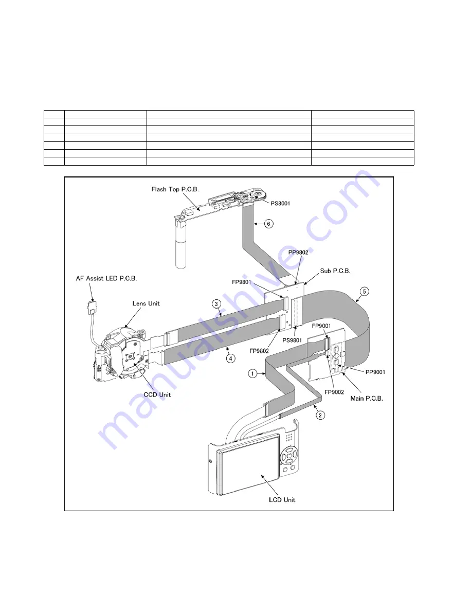
Service Position
This Service Position is used for checking and replacing parts. Use the following Extension cables for servicing.
Table S1 Extension Cable List
CAUTION-1. (When servicing FLASH TOP PCB)
1. Be sure to discharge the capacitor on FLASH TOP PCB.
Refer to “HOW TO DISCHARGE THE CAPACITOR ON FLASH TOP PCB”.
The capacitor voltage is not lowered soon even if the AC Cord is unplugged or the battery is removed.
2. Be careful of the high voltage circuit on FLASH TOP PCB.
3. DO NOT allow other parts to touch the high voltage circuit on FLASH TOP PCB.
No.
Parts No.
Connection
Form
1
RFKZ0354
FP9001 (MAIN) - LCD UNIT
37PIN 0.3 FFC
2
VFK1974
FP9002 (MAIN) - LCD UNIT
4PIN 0.5 FFC
3
VFK1950
FP9801 (SUB) - CCD UNIT
33PIN 0.3 FFC
4
VFK1951
FP9802 (SUB) - LENS UNIT
39PIN 0.3 FFC
5
RFKZ0362
PP9001 (MAIN) - PS9801 (SUB)
100PIN B to B
6
VFK1541
PP9802 (SUB) - PS8001 (FLASH TOP)
40PIN B to B
Содержание Lumix DMC-FX12P
Страница 13: ...13 4 Specifications...
Страница 14: ...14 5 Location of Controls and Components...
Страница 21: ...21 8 Disassembly and Assembly Instructions 8 1 Disassembly Flow Chart 8 2 PCB Location...
Страница 23: ...23 Fig D2 8 3 2 Removal of the LCD Unit Fig D3 8 3 3 Removal of the Front Case Unit Fig D4...
Страница 30: ...30 8 5 3 Assembly for the 1st Lens Frame Unit 8 5 4 Assembly for the 2nd Lens Frame Move Unit...
Страница 31: ...31 8 5 5 Assembly for the Zoom Motor Unit and Master Frange Unit...
Страница 58: ...S7 3 Packing Parts and Accessories Section 2 S 23 307 311 300 312 313 314 303 302 304 305 309 315 308 306...


