


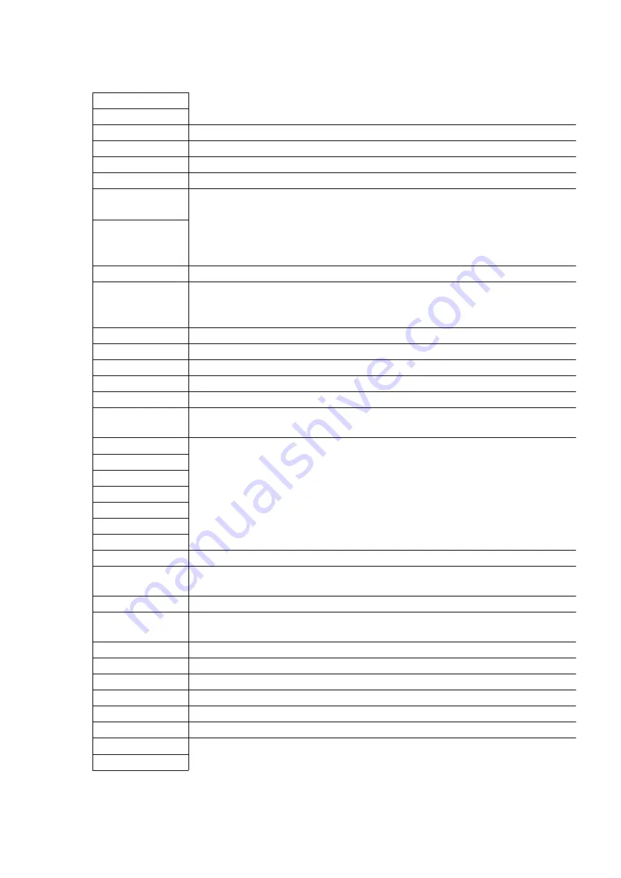
Signal Name
Function
+15VIN
+15V DC
+15V
For C15V DC MOH
+9.4V
For Driver IC +9.4V DC RS-232C
+5V
For Driver IC +5V DC RS-232C
+5VRMT
Reserve
3.3V_BB
+3.3V DC
For pull-up of back board signal line
+3.3VB
+3.3V DC
Backup by a battery
For SRAM (IC301, IC302) backup
+3.3V
+3.3V DC
1.9VB
+1.9V DC
Backup by a battery
For clock function of CPU (IC100)
1.8V
For Core +1.8V DC CPU (IC100)
A[0]-A[25]
Address bus
nAC_ALM
AC alarm signal: This indicates AC voltage cutoff. (L: Alarm condition)
nBACK
Bus Acknowledge: This indicates Bus Acknowledge.
nBATT
This indicates whether external battery is connected or not.L: Connected
nBAT_ALM
Battery Alarm Signal: This indicates the declined voltage of lithium battery. (L:
condition)
nBREQ
Bus Request: Bus request signal
nBS
Bus Cycle Start: Bus cycle start signal
nCASL
Lower Byte Address Column Address Strobe: CAS signal for SDRAM
nCASU
Upper Byte Address Column Address Strobe: CAS signal for SDRAM
CH_SEL[0]
Synchronous Signal for CODEC (For MOH#1/Page#1)
CH_SEL[1]
Synchronous Signal for CODEC (For MOH#2/Page#2)
CH_SEL[2]
Synchronous Signal for CODEC (For RMT)
CKE
Clock Enable: CKE signal for SDRAM
CKIO
Clock I/O Terminal: For bus clock of SDRAM (IC305, IC306) and ASIC (IC101) CPU
(IC100) outputs the clock of four times frequency as many as Source clock (16.384MHz).
nCS0
Chip Select 0: Chip select signal for flash memory
nCS2
Chip Select 2: Chip select signal for the expanded SDRAM (Future Option, Reserve
present.)
nCS3
Chip Select 3: Chip select signal for SDRAM
nCS4
Chip Select 4: Chip select signal for SRAM
nCS5
Chip Select 5: Chip select signal for ASIC
nCS6
Chip Select 6: Chip select signal for USB I/F and SD card I/F
nCS_FLASH0
Chip Select for Flash memory0: CS signal for IC303
nCS_FLASH1
Chip Select for Flash memory1: CS signal for IC304 (reserve)
nCS_SDB0
Chip Select for Sd card I/F
nCS_SDB1
Reserve
33
Содержание KX-TDA100AL
Страница 9: ...5 2 SYSTEM COMPONENTS 9 ...
Страница 13: ...13 ...
Страница 15: ... Null slot Null slot is not available for any optional service card RUN Indicator 15 ...
Страница 19: ...3 Remove the Hook And remove the Top Cover 4 Remove nine Screws B 5 Remove the Back Cover 19 ...
Страница 22: ...8 2 2 Voice TDM Highway Bus Block Diagram 22 ...
Страница 23: ...8 2 3 Voice Bus Logical Assignment 23 ...
Страница 25: ...8 3 2 EC Bus System Connection Diagram 25 ...
Страница 26: ...8 3 3 System Control and Analog Signal Connection Diagram 26 ...
Страница 27: ...8 3 4 Power Supply System Connection Diagram 27 ...
Страница 29: ... 5VRMT unused for remote card 5V for RS 232C driver receiver 9 1 2 Description of Each Part 29 ...
Страница 30: ...30 ...
Страница 41: ...41 ...
Страница 42: ...42 ...
Страница 43: ...43 ...
Страница 44: ...44 ...
Страница 45: ...11 1 2 Phone Call 45 ...
Страница 46: ...11 1 3 Paging 46 ...
Страница 47: ...47 ...
Страница 48: ...48 ...
Страница 49: ...11 1 4 MOH Using 49 ...
Страница 50: ...50 ...
Страница 51: ...51 ...
Страница 52: ...11 1 5 USB Connection 52 ...
Страница 53: ...53 ...
Страница 54: ...11 1 6 RS 232C Connection 54 ...
Страница 55: ...55 ...
Страница 56: ...11 1 7 SD Card I F 11 1 8 Other 56 ...
Страница 57: ...12 DIAGNOSIS 12 1 DIAGNOSIS FEATURES 57 ...
Страница 66: ...7 Click Card Test 8 Click OK 9 Click Cancel 13 IC DATA 13 1 IC101 66 ...
Страница 76: ...76 ...
Страница 77: ...16 1 EXTENSION BOARDS FOR SERVICING 17 ACCESSORIES AND PACKING MATERIALS 77 ...
Страница 100: ......
Страница 110: ...Waveform 7 Waveform 8 20MHz 12MHz ...
Страница 118: ......
Страница 119: ......
Страница 120: ......
Страница 121: ......
Страница 122: ......
Страница 123: ......
Страница 124: ......
Страница 125: ......