166
KX-FG2452CX
12.5.15.1.4. Test Range Check
Circuit block which range is defective can be found by the following check.
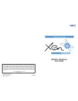
CHART1: Setting of TX Power and RX Sensitivity in Range Confirmation TX TEST, RX TEST
Note:
(*1):
Item
BU (Base Unit) Check
HS (HandSet) Check
Range Confirmation TX TEST
(TX Power check)
HS, BU Mode:
[Test Link Mode] (*1)
1. Register Regular HS to BU (to be checked).
2. Set BU to “Test Link mode”.
3. Set Regular HS to “Test Link mode”.
*Set TX Power and RX Sensitivity of the BU and the
Regular HS by CHART1.
* At distance of about 20m between HS and BU,
Link OK = TX Power of the BU is OK.
No Link = TX Power of the BU is NG.
1. Register HS (to be checked) to Regular BU.
2. Set Regular BU to “Test Link mode”.
3. Set HS to “Test Link mode”.
*Set TX Power and RX Sensitivity of the HS and the
Regular BU by CHART1.
* At distance of about 20m between HS and BU,
Link OK = TX Power of the HS is OK.
No Link = TX Power of the HS is NG.
Range Confirmation RX TEST
(RX sensitivity check)
HS, BU Mode:
[Test Link Mode] (*1)
1. Register Regular HS to BU (to be checked).
2. Set BU to “Test Link mode”.
3. Set Regular HS to “Test Link mode”.
*Set TX Power and RX Sensitivity of the BU and Regular
HS by CHART1.
* At distance of about 20m between HS and BU,
Link OK= RX Sensitivity of the BU is OK.
No Link = RX Sensitivity of the BU is NG.
1. Register HS (to be checked) to Regular BU.
2. Set Regular BU to “Test Link mode”.
3. Set HS to “Test Link mode”.
* Set TX Power and RX Sensitivity of Checking_HS and
Regular_BU by CHART1.
* At distance of about 20m between HS and BU,
Link OK= RX Sensitivity of the HS is OK.
No Link = RX Sensitivity of the HS is NG
BU (to be checked)
Regular_HS
TX Power
RX Sens.
TX Power
RX Sens.
BU (Base Unit) TX Power Check
High
High
High
Low
BU (Base Unit) RX Sensitivity Check
High
High
Low
High
HS (to be checked)
Regular_BU
TX Power
RX Sens.
TX Power
RX Sens.
HS (Handset) TX Power Check
High
High
High
Low
HS (Handset) RX Sensitivity Check
High
High
Low
High
Содержание KX-FG2452CX
Страница 10: ...10 KX FG2452CX 6 Technical Descriptions 6 1 Connection Diagram ...
Страница 14: ...14 KX FG2452CX 6 3 2 Memory Map ...
Страница 23: ...23 KX FG2452CX 6 4 2 Block Diagram ...
Страница 25: ...25 KX FG2452CX ...
Страница 38: ...38 KX FG2452CX b Redundancy Compression Process Coding Mode This unit uses one dimensional MH format ...
Страница 61: ...61 KX FG2452CX 6 14 5 7 Power Supply Circuit Voltage is supplied separately to each block ...
Страница 76: ...76 KX FG2452CX 9 2 3 Other Features ...
Страница 81: ...81 KX FG2452CX 10 2 1 1 Test Burst Mode and Test TX CW Mode ...
Страница 82: ...82 KX FG2452CX 10 2 1 2 RX CW Test Mode ...
Страница 83: ...83 KX FG2452CX 10 2 1 3 Test Link Mode ...
Страница 93: ...93 KX FG2452CX 11 3 2 Service Mode Settings Note The above values are the default values ...
Страница 101: ...101 KX FG2452CX Countermeasure ...
Страница 102: ...102 KX FG2452CX REFERENCE Test Mode P 77 ...
Страница 103: ...103 KX FG2452CX REFERENCE Test Mode P 77 ...
Страница 104: ...104 KX FG2452CX REFERENCE Test Mode P 77 ...
Страница 105: ...105 KX FG2452CX REFERENCE Test Mode P 77 ...
Страница 106: ...106 KX FG2452CX ...
Страница 107: ...107 KX FG2452CX REFERENCE Test Mode P 77 ...
Страница 108: ...108 KX FG2452CX REFERENCE Test Mode P 77 ...
Страница 112: ...112 KX FG2452CX ...
Страница 137: ...137 KX FG2452CX ...
Страница 144: ...144 KX FG2452CX I O and Pin No Diagram ...
Страница 146: ...146 KX FG2452CX Other NG example while the power is ON and the LCD displays the following ...
Страница 147: ...147 KX FG2452CX 12 5 5 2 NG Example ...
Страница 149: ...149 KX FG2452CX ...
Страница 152: ...152 KX FG2452CX Note Check to the SP Phone Rx Tx signal routes Refer to Check Sheet for Signal Route P 148 ...
Страница 154: ...154 KX FG2452CX 12 5 8 2 Troubleshooting Flow Chart ...
Страница 159: ...159 KX FG2452CX 12 5 11 CIS Contact Image Sensor Section Note 1 Test Mode P 77 Refer to Scanning Block P 26 ...
Страница 160: ...160 KX FG2452CX 12 5 12 Thermal Head Section Note Refer to Thermal Head P 24 ...
Страница 167: ...167 KX FG2452CX 12 5 15 1 5 RF DSP Interface Signal Wave Form ...
Страница 169: ...169 KX FG2452CX 13 Service Fixture Tools ...
Страница 173: ...173 KX FG2452CX 14 2 5 Handset Section REFERENCE E 1 How to Remove the Handset Board P 197 ...
Страница 174: ...174 KX FG2452CX 14 3 Disassembly Procedure 14 3 1 How to Remove the Image Sensor CIS ...
Страница 175: ...175 KX FG2452CX 14 3 2 How to Remove the Thermal Head ...
Страница 176: ...176 KX FG2452CX ...
Страница 177: ...177 KX FG2452CX 14 3 3 How to Remove the Bottom Frame ...
Страница 178: ...178 KX FG2452CX 14 3 4 How to Remove the P C Boards and Speaker ...
Страница 179: ...179 KX FG2452CX 14 3 5 How to Remove the Power Supply Board and AC Cord ...
Страница 180: ...180 KX FG2452CX 14 3 6 How to Remove the Gear Block and Separation Roller ...
Страница 181: ...181 KX FG2452CX 14 3 7 How to Remove the Gears Motors and Arms of the Gear Block ...
Страница 182: ...182 KX FG2452CX ...
Страница 183: ...183 KX FG2452CX 14 3 8 How to Remove the Charger Case ...
Страница 184: ...184 KX FG2452CX 14 3 9 How to Remove the Back Cover ...
Страница 185: ...185 KX FG2452CX 14 3 10 How to Remove the Platen Roller and Lock Lever ...
Страница 186: ...186 KX FG2452CX ...
Страница 187: ...187 KX FG2452CX 14 3 11 How to Remove the Pickup Roller and Antenna ...
Страница 188: ...188 KX FG2452CX 14 3 12 How to Remove the Operation Panel ...
Страница 189: ...189 KX FG2452CX 14 3 13 How to Remove the Operation Board MIC Board and LCD ...
Страница 190: ...190 KX FG2452CX 14 3 14 How to Remove the Separation Holder and Exit Roller ...
Страница 191: ...191 KX FG2452CX 14 3 15 Installation Position of the Lead Wires 14 3 15 1 Lower Section ...
Страница 192: ...192 KX FG2452CX ...
Страница 193: ...193 KX FG2452CX ...
Страница 194: ...194 KX FG2452CX ...
Страница 195: ...195 KX FG2452CX 14 3 15 2 Operation Panel Section ...
Страница 196: ...196 KX FG2452CX 14 3 15 3 Back Cover Section ...
Страница 197: ...197 KX FG2452CX 14 3 16 How to Remove the Handset Board ...
Страница 198: ...198 KX FG2452CX 14 3 16 1 How to Replace the Handset LCD ...
Страница 213: ...213 KX FG2452CX 16 2 3 4 Copying Note See Sensor Locations in Sensors and Switches P 29 REFERENCE Sensor Section P 157 ...
Страница 219: ...219 KX FG2452CX 17 1 3 Operation Board Microphone Board 17 1 4 Power Supply Board 17 1 5 Interface Board ...
Страница 220: ...220 KX FG2452CX 17 1 6 Handset Board ...
Страница 223: ...223 KX FG2452CX 17 3 Test Chart 17 3 1 ITU T No 1 Test Chart ...
Страница 224: ...224 KX FG2452CX 17 3 2 ITU T No 2 Test Chart ...
Страница 225: ...225 KX FG2452CX 17 3 3 Test Chart ...
Страница 251: ...251 KX FG2452CX 20 3 Explanation of RF unit Terminals RF Unit 20 3 1 IC901 ...
Страница 253: ...253 KX FG2452CX 21 1 2 Operation Panel Section ...
Страница 254: ...254 KX FG2452CX 21 1 3 Upper Cabinet Section ...
Страница 255: ...255 KX FG2452CX 21 1 4 Back Cover Section ...
Страница 256: ...256 KX FG2452CX ...
Страница 257: ...257 KX FG2452CX 21 1 5 Lower Cabinet Section ...
Страница 258: ...258 KX FG2452CX 21 1 6 Gear Block Section ...
Страница 259: ...259 KX FG2452CX ...
Страница 261: ...261 KX FG2452CX 21 1 8 Screws ...
Страница 262: ...262 KX FG2452CX 21 1 9 Accessories and Packing Materials ...