29
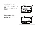
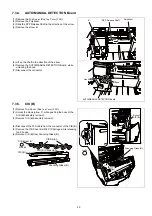
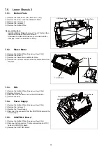
7.3.4.
AUTO/MANUAL DETECTION Board
7.3.5.
CIS (B)
(1) Remove the Top Cover. (See
))
(2) Remove the Polyslider.
(3) Slide the DFP Release Shaft in the direction of the arrow.
(4) Remove the screw B.
(5) Lift up the shaft in the direction of the arrow.
(6) Remove the AUTO/MANUAL DETECTION Board, while
unlocking the hook.
(7) Disconnect the connector.
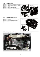
(1) Remove Top Cover. (See
(2) Unlock the Hook (arrow
1
), while pushing the boss of the
CIS (B) Assembly (arrow
2
).
(3) Remove CIS (B) Assembly (arrow
3
).
(4) Disconnect the FFC cable from the connector of the CIS (B).
(5) Remove the CIS Cover B with 2 CIS Springs, while releasing
the 9 hooks.
(6) Remove CIS (B) from Scanning Glass (B).
Polyslider
DFP Release Shaft
B
Boss
Hook
AUTO/MANUAL DETECTION Board
CIS Cover B
Hooks
CIS Spring
CIS (B) Connector
CIS (B)
Scanning Glass (B)
Scanning Glass (B)
Hook
Boss of
CIS (B)
1
3
2
Содержание KV-S1057C
Страница 7: ...7...
Страница 9: ...9 3 Location of Controls and Components 3 1 Main Unit...
Страница 10: ...10...
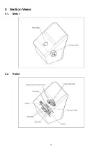
Страница 16: ...16 5 Section Views 5 1 Motor 5 2 Roller...
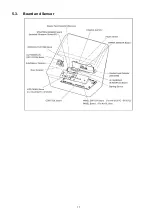
Страница 17: ...17 5 3 Board and Sensor...
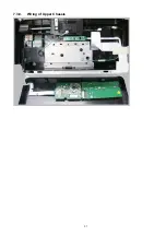
Страница 31: ...31 7 3 8 Wiring of Upper Chassis...
Страница 128: ...128 14 Exploded View and Replacement Parts List...
Страница 133: ...133 14 3 Feed Tray Assembly 302 305 302 303 307 301 306 305 302 304 Feed Tray Assembly...
Страница 180: ...180 15 Appendix The extract from an Operating Manual N K KVS1057C KVS1027C KVSL1066 KVSL1056 KVSL1055 KVSL1036 KVSL1035...
Страница 188: ...Index 74 8 Operating Manual Table of Contents...
Страница 214: ...3 Attach the feed tray A to the unit 1 4 Attach the mixed batch card guide A to the unit 1 34 Operating Manual Operation...
Страница 255: ...PNQX6995ZA DD0914HS0 Panasonic System Networks Co Ltd 2014...

