3
2
Device Installation
Important
• Make sure that the installation area is strong enough to hold the product, such as a
concrete ceiling.
• Install the camera in the foundation area of the architecture or where sufficient strength
is assured.
• If a wall or ceiling board such as plasterboard is too weak to support the total weight, the
area shall be sufficiently reinforced.
Please see Figure 3-1 and Figure 3-2.
2.1
Installation Steps
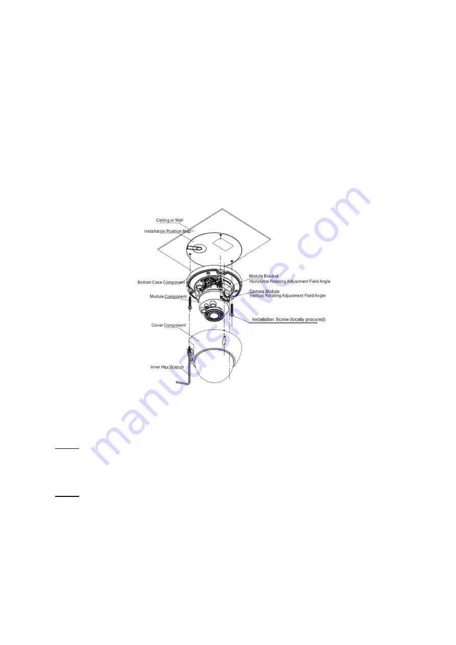
Figure 2-1
Please follow the steps listed below to install the device. Please refer to Figure 2-1 for reference.
Step 1
Use inner hex wrench in the accessories bag to open dome enclosure by unfastening three inner hex
screws on enclosure.
Step 2
Please take the installation position map in the accessories bag, and then paste it on the ceiling or the
wall according to your monitor area requirements and use a pen to mark the positions of the screws
and cable mounting hole in the ceiling or wall.
Note:
If use pulls out cable from top of installation surface, you must dig an exit hole on installation
surface according to the installation position map.