12.5 Clamp Assembly Removal and Installation
(1) Remove the fro n t plate as described in section
12
.
2
.
(2) Remove the shield plate as described in section
12.1 step (1).
(3) Remove the tw o clamp assembly m ounting
screws and take o ut the clamp assembly.
(4) Reverse the above procedure to reinstall.
(1) Remove the shield plate as described in section
12.1 step (1).
(2) Disconnect the J3 connector from PCB.
(3) Draw out the pins o f the w rite protect sensor
assembly from the fo llo w in g locations on the
J3 co n n e cto r: N o 9 ,11.
A t th a t tim e, draw o ut the pins w ith liftin g the
stopper on the connector.
(4) Draw o ut the pins o f the index sensor assembly
from the fo llo w in g locations on the J3
c o nn e cto r: No5, 7.
A t th a t tim e, draw out the pins w ith liftin g the
stopper on the connector.
(5) Remove the w rite protect sensor m ounting
screw and index sensor m ounting screw
respectively.
(6) Reverse the above procedure to reinstall.
(7) When reinstalling the w rite protect sensor,
exercise care so th a t the leads and w rite protect
sensor w ill not project from the bottom and
side o f the base.
(8) A fte r index sensor installation, adjust the index
burst as described in section 9.8.
12.6 Write Protect Sensor Assembly and Index
Sensor Assembly Removal and Installation
Fig. 12-5 Clamp Assembly Removal
Содержание JU-475-4
Страница 1: ...ORDER NO MSD891122000 Service Manual Flexible Disk Storage Drive JU 475 4 Panasonic ...
Страница 6: ...6 2 Troubleshooting Flowchart Table6 1 Troubleshooting Flowchart 4 ...
Страница 14: ...10 TEST POINTS Printed Circuit Board Top View GND Vout Vout GND TRK0 TP 8 kJ 1 2 ...
Страница 30: ...17 CIRCUIT BOARD JU 475 4AGG Component Side Top 28 TP5 L 6 ...
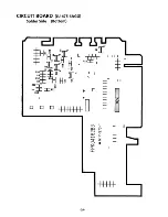
Страница 31: ...CIRCUIT BOARD JU 475 4AGG Solder Side Bottom 29 ...
Страница 34: ...Matsushita Communication industrial Co Ltd Memory Systems Division ...


