


26
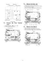
7.26. Remove the Cabinet-fixing
metal (B) (Upper)
1. Remove the cabinet assy (glass). (See section 7.25.)
2. Remove the screws (
×
6 ).
3. Remove the Cabinet-fixing metal (B).
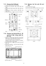
7.27. Remove the C1-Board
1. Remove the Fan unit (R). (See section 7.19.)
2. Remove the Cabinet-fixing metal (A) and (B). (See sec-
tion 7.21. and 7.26.)
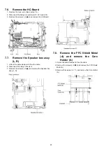
3. Remove the flexible cables holder fastening screws (
×
10
).
4. Disconnect the flexible cables (CA1, CA2, CA3, CA4 and
CA5).
5. Disconnect the flexible cables (C10 and C11).
6. Remove the screws (
×
5
) and remove the C1-Board.
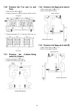
7.28. Remove the C2-Board
1. Remove the Fan unit (L). (See section 7.20.)
2. Remove the Cabinet-fixing metal (A) and (B). (See sec-
tion 7.21. and 7.26.)
3. Remove the flexible cables holder fastening screws (
×
10
).
4. Disconnect the flexible cables (CA6, CA7, CA8, CA9, and
CA10).
5. Disconnect the flexible cables (C20, C21, C22 and C23).
6. Remove the screws (
×
5
) and remove the C2-Board.
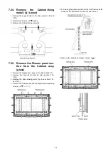
7.29. Remove the C3-Board
1. Remove the Fan unit (L). (See section 7.20.)
2. Remove the Cabinet-fixing metal (A) and (B). (See sec-
tion 7.21. and 7.26.)
3. Remove the flexible cables holder fastening screws (
×
10
).
4. Disconnect the flexible cables (CA11, CA12, CA13, CA14
and CA15).
5. Disconnect the flexible cable (C33).
6. Disconnect the connector (C32).
7. Remove the screws (
×
5
) and remove the C3-Board.
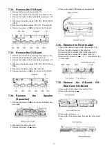
7.30. Remove the Cabinet-fixing
metal (B) (Lower)
1. Remove the Cabinet assy (glass). (See section 7.25.)
2. Remove the screws (
×
4 ).
3. Remove the Cabinet-fixing metal (B).
7.31. Remove the C4-Board
1. Remove the Cabinet-fixing metal (B). (See section 7.30.)
2. Remove the Vertical Bar (L). (See section 7.18.)
3. Remove the flexible cables holder fastening screws (
×
10
).
4. Disconnect the flexible cables (CB11, CB12, CB13, CB14
and CB15).
5. Disconnect the flexible cable (C41).
6. Disconnect the connector (C45).
7. Remove the screws (
×
5
) and remove the C4-Board.
Содержание ITD0810090CE
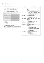
Страница 6: ...6 3 2 Applicable signals ...
Страница 16: ...16 6 4 No Picture ...
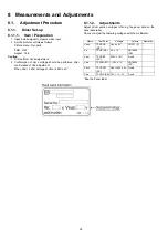
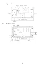
Страница 32: ...32 8 1 4 Adjustment Volume Location 8 1 5 Test Point Location ...
Страница 40: ...40 ...
Страница 42: ...42 10 3 Wiring 2 ...
Страница 43: ...43 10 4 Wiring 3 ...
Страница 44: ...44 ...
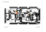
Страница 45: ...45 11 Schematic Diagram 11 1 Schematic Diagram Note ...
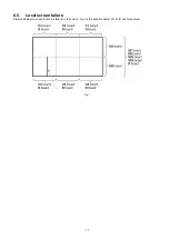
Страница 132: ...132 13 1 2 Fan and cable location ...
Страница 133: ...133 13 1 3 Packing ...
Страница 137: ...137 13 2 Electrical Replacement Parts List 13 2 1 Replacement Parts List Notes ...


