background image

NOTE:

The U.S. Government standard is 5 mW/cm

2

while in the

customer’s home. 2mW/cm

2

stated here is our own

voluntary standard. (1mW/cm

2

for Canada)

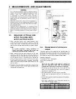
4.1. Equipment

     • 

• 

• 

• 

Electromagnatic radiation monitor

     • 

• 

• 

• 

Glass thermometer 212°F or 100°C

     • 

• 

• 

• 

600cc glass beaker

4.2. Procedure for measuring

radiation leakage

Note before measuring.

     • 

• 

• 

• 

Do not exceed meter full scale deflection. Leakage monitor
should initially be set to the highest scale.

     • 

• 

• 

• 

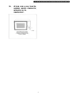
To prevent false readings the test probe should be held by
the grip portion of the handle only and moved along the
shaded

area

in

Figure

no

faster

than

1

inch/sec

(2.5cm/sec).

     • 

• 

• 

• 

Leakage with the outer panel removed ...... less than
5mW/cm

2

.

     • 

• 

• 

• 

Leakage for a fully assembled oven with door normally
closed ...... less than 2mW/cm

2

(1mW/cm

2

for Canada).

     • 

• 

• 

• 

Leakage for a fully assembled oven [Before the latch switch
(primary) is interrupted] while pulling the door ...... less than
2mW/cm

2

.

 1. Pour 275 ± 15cc (9ozs

s

± 1/2oz) of 20°C ± 5°C (68° ± 9°F)

water in a beaker which is graduated to 600cc, and place in
the center of the oven.

 2. Set the radiation monitor to 2450MHz and use it following

the manufacturer´s recommended test procedure to assure
correct results.

 3. When measuring the leakage, always use the 2 inch (5cm)

spacer supplied with the probe.

 4. Tap the start pad or set the timer and with the magnetron

oscillating, measure the leakage by holding the probe
perpendicular to the surface being measured.

4.2.1. Measurement with the outer panel

removed.

Whenever you replace the magnetron, measure for radiation
leakage before the outer panel is installed and after all
necessary components are replaced or adjusted. Special care
should be taken in measuring around the magnetron.

4.2.2. Measurements with a fully

assembled oven.

After all components, including outer panel are fully assembled,
measure for radiation leakage around the door periphery, the
door viewing window, the exhaust opening and air inlet
openings.

4.3. Record keeping and

notification after measurement

     • 

• 

• 

• 

After any adjustment or repair to a microwave oven, a
leakage reading must be taken. Record this leakage
reading on the repair ticket even if it is zero.

A copy of this repair ticket and the microwave leakage
reading should be kept by repair facility.

     • 

• 

• 

• 

Should the radiation leakage be more than 2 mW/cm

2

(1mW/cm for Canada) after determining that all parts are in
good

condition,

functioning

properly,

and

genuine

replacement parts as listed in this manual have been used,
immediately notify PASC, PSC or PCI.

4 PROCEDURE FOR MEASURING MICROWAVE ENERGY

LEAKAGE

8

NN-T583SF / NN-T563SF / NN-T563SAF / NN-S563 NN-S553 / NN-S543 NN-S533 / NN-S523 NN-S513 / NN-S503

Содержание Inverter NN-S503

Страница 1: ...ibution is a violation of law NN T583SF NN T563SF NN T563SAF NN S563 NN S553 NN S543 NN S533 NN S523 NN S513 NN S503 APH USA CPH CANADA Microwave Oven Please file and use this specified manual together with the service manual for Model NN S560BF WF ORDER NO SIMMC0001002C3 ORDER NO SIMMC 0301001A1 E1 ...

Страница 2: ...2 NN T583SF NN T563SF NN T563SAF NN S563 NN S553 NN S543 NN S533 NN S523 NN S513 NN S503 ...

Страница 3: ...3 NN T583SF NN T563SF NN T563SAF NN S563 NN S553 NN S543 NN S533 NN S523 NN S513 NN S503 ...

Страница 4: ...IALS 13 9 ESCUTCHEON BASE ASSEMBLY NN S APH CPH 14 10 ESCUTCHEON BASE ASSEMBLY NN T APH CPH 15 11 PACKING AND ACCESORIES 16 12 DIGITAL PROGRAMMER CIRCUIT NN T583SF APH CPH 17 13 DIGITAL PROGRAMMER CIRCUIT NN T563SF APH NN T563SAF APH 19 14 DIGITAL PROGRAMMER CIRCUIT NN S APH CPH 21 15 DIGITAL PROGRAMMER CIRCUIT 23 CONTENTS Page Page 4 NN T583SF NN T563SF NN T563SAF NN S563 NN S553 NN S543 NN S533 ...

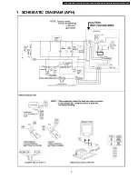
Страница 5: ...1 SCHEMATIC DIAGRAM APH 5 NN T583SF NN T563SF NN T563SAF NN S563 NN S553 NN S543 NN S533 NN S523 NN S513 NN S503 ...

Страница 6: ...2 SCHEMATIC DIAGRAM CPH 6 NN T583SF NN T563SF NN T563SAF NN S563 NN S553 NN S543 NN S533 NN S523 NN S513 NN S503 ...

Страница 7: ...cedures 3 2 Measurement of microwave output The output power of the magnetron can be determined by performing IEC standard test procedures However due to the complexity of IEC test procedures it is recommended to test the magnetron using the simple method outlined below Necessary Equipment 1 liter beaker Glass thermometer Wrist watch or stopwatch NOTE Check the line voltage under load Low voltage ...

Страница 8: ...spacer supplied with the probe 4 Tap the start pad or set the timer and with the magnetron oscillating measure the leakage by holding the probe perpendicular to the surface being measured 4 2 1 Measurement with the outer panel removed Whenever you replace the magnetron measure for radiation leakage before the outer panel is installed and after all necessary components are replaced or adjusted Spec...

Страница 9: ...4 4 At least once a year have the radiation monitor checked for calibration by its manufacturer 9 NN T583SF NN T563SF NN T563SAF NN S563 NN S553 NN S543 NN S533 NN S523 NN S513 NN S503 ...

Страница 10: ...5 EXPLODED VIEW AND PARTS LIST 10 NN T583SF NN T563SF NN T563SAF NN S563 NN S553 NN S543 NN S533 NN S523 NN S513 NN S503 ...

Страница 11: ...AP CABINET BODY U 1 S BF 6 F110D5Y30HAP CABINET BODY U 1 S WF 7 F200A5Y30AP OVEN U 1 T APH CPH S563 APH CPH S533 APH 7 F200A5Y40AP OVEN U 1 S APH CPH EXCEPT S563 APH CPH S533 APH 8 F20555L00AP COVER 1 9 F21315Y00AP PULLY SHAFT 1 10 F2177 F80 WASHER 1 11 F290D9330AP ROLLER RING U 1 12 F3020 1200 DOOR HOOK 1 T APH CPH 12 F30208790XN DOOR HOOK 1 S APH CPH 13 F3097 5L00 LATCH SPRING 1 S APH CPH 14 F31...

Страница 12: ...EW 1 FOR COVER 42 XTCA4 12AFK SCREW 1 FOR CABINET BODY SIDE S BF 42 XTCA4 12AFW SCREW 1 FOR CABINET BODY SIDE S WF 42 XTCA4 12AFS SCREW 1 FOR CABINET BODY SIDE S MF 42 XTCA4 12AFM SCREW 1 FOR CABINET BODY SIDE T SF SAF 43 XTTAFE4T12A0 SCREW 4 FOR CABINET BODY 45 F65855X00AP INVERTER BRACKET 1 T APH 45 F65855W00AP INVERTER BRACKET 1 EXCEPT T APH 46 F03345W20AP MENU LABEL 1 T583 APH 46 F03345Y30AP M...

Страница 13: ...A 1 D7 F31465Y00SAP DOOR SCREEN B 1 T583SF APH CPH D7 F31465Y20BAP DOOR SCREEN B 1 T563SF APH T563SAF APH D7 F31465Y30BAP DOOR SCREEN B 1 S BF MF EXCEPT S503BF APH D7 F31465Y30HAP DOOR SCREEN B 1 S WF EXCEPT S503WF APH D7 F31464T00BAP DOOR SCREEN B 1 S503BF APH D7 F31464T00HAP DOOR SCREEN B 1 S503WF APH D8 F02459660AP DHHS LABEL 1 T APH S503 APH D8 F04114180CP DHHS LABEL 1 T CPH 8 WIRING MATERIALS...

Страница 14: ...630Y5Y60HAP MEMBRANE SWITCH U 1 S503WF APH E2 F630Y5Y30BCP MEMBRANE SWITCH U 1 S563BF CPH E2 F630Y5Y30HCP MEMBRANE SWITCH U 1 S563WF CPH E2 F630Y5Y30SCP MEMBRANE SWITCH U 1 S563MF CPH E2 F630Y5Y70HCP MEMBRANE SWITCH U 1 S533WF CPH E2 F630Y5Y80HCP MEMBRANE SWITCH U 1 S523WF CPH E2 F630Y5Y90HCP MEMBRANE SWITCH U 1 S513WF CPH E3 F80345L00BAP ESCUTCHEON BASE 1 S BF EXCEPT S533BF APH S503BF APH E3 F803...

Страница 15: ...F CPH E11 F800L5Y00BAP CONTROL PANEL AU 1 T APH CPH E12 F630Y5Y00SAP MEMBRANE SWITCH U 1 T583SF APH E12 F630Y5Y20SAP MEMBRANE SWITCH U 1 T563SF APH T563SAF APH E12 F630Y5Y00SCP MEMBRANE SWITCH U 1 T583SF CPH E13 F82565Y00AP DOOR OPENING LEVEL 1 T APH CPH E14 F90095X00AP BACK PANEL 1 T APH CPH E15 F00075Y00SCP NAME PLATE 1 T583SF CPH 15 NN T583SF NN T563SF NN T563SAF NN S563 NN S553 NN S543 NN S533...

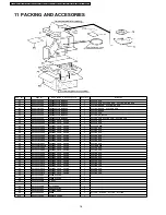
Страница 16: ...1 S553BF APH P2 F01025Y40HAP PACKING CASE PAPER 1 S553WF APH P2 F01025W70BAP PACKING CASE PAPER 1 S543BF APH P2 F01025W70HAP PACKING CASE PAPER 1 S543WF APH P2 F01025W70BAPW PACKING CASE PAPER 1 S543BFW APH P2 F01025Y70BAP PACKING CASE PAPER 1 S533BF APH P2 F01025Y70HAP PACKING CASE PAPER 1 S533WF APH P2 F01025Y60BAP PACKING CASE PAPER 1 S503BF APH P2 F01025Y60HAP PACKING CASE PAPER 1 S503WF APH P...

Страница 17: ...12 DIGITAL PROGRAMMER CIRCUIT NN T583SF APH CPH SCHEMATIC DIAGRAM 17 NN T583SF NN T563SF NN T563SAF NN S563 NN S553 NN S543 NN S533 NN S523 NN S513 NN S503 ...

Страница 18: ...18 NN T583SF NN T563SF NN T563SAF NN S563 NN S553 NN S543 NN S533 NN S523 NN S513 NN S503 ...

Страница 19: ...13 DIGITAL PROGRAMMER CIRCUIT NN T563SF APH NN T563SAF APH SCHEMATIC DIAGRAM 19 NN T583SF NN T563SF NN T563SAF NN S563 NN S553 NN S543 NN S533 NN S523 NN S513 NN S503 ...

Страница 20: ...20 NN T583SF NN T563SF NN T563SAF NN S563 NN S553 NN S543 NN S533 NN S523 NN S513 NN S503 ...

Страница 21: ...14 DIGITAL PROGRAMMER CIRCUIT NN S APH CPH SCHEMATIC DIAGRAM 21 NN T583SF NN T563SF NN T563SAF NN S563 NN S553 NN S543 NN S533 NN S523 NN S513 NN S503 ...

Страница 22: ...22 NN T583SF NN T563SF NN T563SAF NN S563 NN S553 NN S543 NN S533 NN S523 NN S513 NN S503 ...

Страница 23: ...D 4 D184 D189 AESQPY1112H CHIP LED 6 T583 APH CPH IC1 MN101C54CEH L S I 1 T583 APH CPH IC1 MN101C589EB L S I 1 T563SF APH T563SAF APH IC1 MN101C589EA L S I 1 S APH CPH IC480 AEICUPC358G2 IC 1 T583 APH CPH S563 APH CPH S533 APH Q226 AESA14EKE CHIP DIGI TRANSISTOR 1 Q182 AESC23JKE CHIP DIGI TRANSISTOR 1 Q210 AESC23JKE CHIP DIGI TRANSISTOR 1 S APH CPH Q223 Q224 AESC23JKE CHIP DIGI TRANSISTOR 2 T APH ...

Страница 24: ... APH CPH R440 AERJ06J512R CHIP RESISTOR 1 5 1K 1 16W 5 R486 AERJ06J684R CHIP RESISTOR 1 680K 1 16W 5 T APH CPH S563 APH CPH S533 APH R10 R11 AERDY2TJ102T CARBON RESISTOR 2 1K 1 4W 5 R290 AERDY2TJ103T CARBON RESISTOR 1 10K 1 4W 5 S APH CPH R12 R180 AERDY2TJ103T CARBON RESISTOR 2 10K 1 4W 5 T APH CPH R290 AERDY2TJ104T CARBON RESISTOR 1 100K 1 4W 5 T APH CPH VZ1 AEVNNV6TL103 VARISTOR 1 10KΩ Ω Ω Ω S A...

Отзывы: