


60
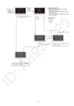
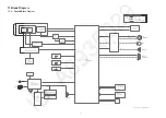
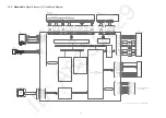
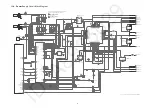
13 Schematic Diagram
Please click the radio button for “Diagrams II / Parts List” on the menu bar in XML Service Manual.
If you want to print, please click the icon button for “Print” on the icon bar and select the item.
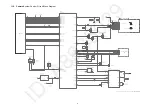
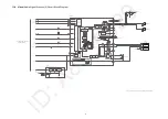
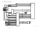
14 Printed Circuit Board
Please click the radio button for “Diagrams II / Parts List” on the menu bar in XML Service Manual.
If you want to print, please click the icon button for “Print” on the icon bar and select the item.
15 Exploded View and Replacement Parts List
Please click the radio button for “Diagrams II / Parts List” on the menu bar in XML Service Manual.
If you want to print, please click the icon button for “Print” on the icon bar and select the item.
Содержание HC-V180PP
Страница 11: ...11 ...
Страница 13: ...13 ...
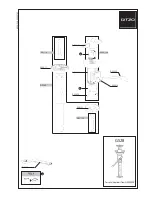
Страница 23: ...23 8 2 PCB Location ...
Страница 26: ...26 8 3 1 Removal of the Side Case L Unit Fig D1 Fig D2 ...
Страница 28: ...28 8 3 4 Removal of the Lens Frame Unit Fig D8 Fig D9 ...
Страница 29: ...29 8 3 5 Removal of the Camera Lens Unit Fig D10 8 3 6 Removal of the Main P C B SD Holder P C B Fig D11 ...
Страница 30: ...30 Fig D12 8 3 7 Removal of the Top Operation BATT Catcher P C B Fig D13 ...
Страница 31: ...31 8 3 8 Removal of the R Frame Unit Speaker LCD Unit Fig D14 Fig D15 ...
Страница 32: ...32 8 3 9 Removal of the Monitor P C B LCD Hinge Unit Light Guide Plate Unit LCD Panel Unit Fig D16 Fig D17 ...
Страница 33: ...33 Fig D18 8 3 10 Removal of the Spring Holder Bar rier Lever Fig D19 ...
Страница 35: ...35 8 3 13 Removal of the MOS Unit IR Cut Grass Fig D22 Fig D23 ...
Страница 36: ...36 Fig D24 8 3 14 Removal of the 2nd Stepping Motor Fig D25 ...
Страница 37: ...37 Fig D26 8 3 15 Removal of the 3rd Stepping Motor Fig D27 ...
Страница 38: ...38 Fig D28 8 3 16 Removal of the Focus Motor Fig D29 ...
Страница 39: ...39 Fig D30 ...
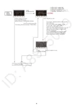
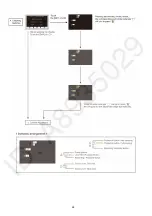
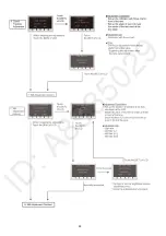
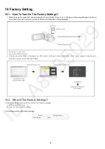
Страница 43: ...43 9 1 2 Adjustment Items Adjustment item as follows ...
Страница 46: ...46 ...
Страница 47: ...47 ...
Страница 48: ...48 ...
Страница 49: ...49 ...
Страница 50: ...50 ...
Страница 51: ...51 ...