background image

16

Part Names and Functions

2

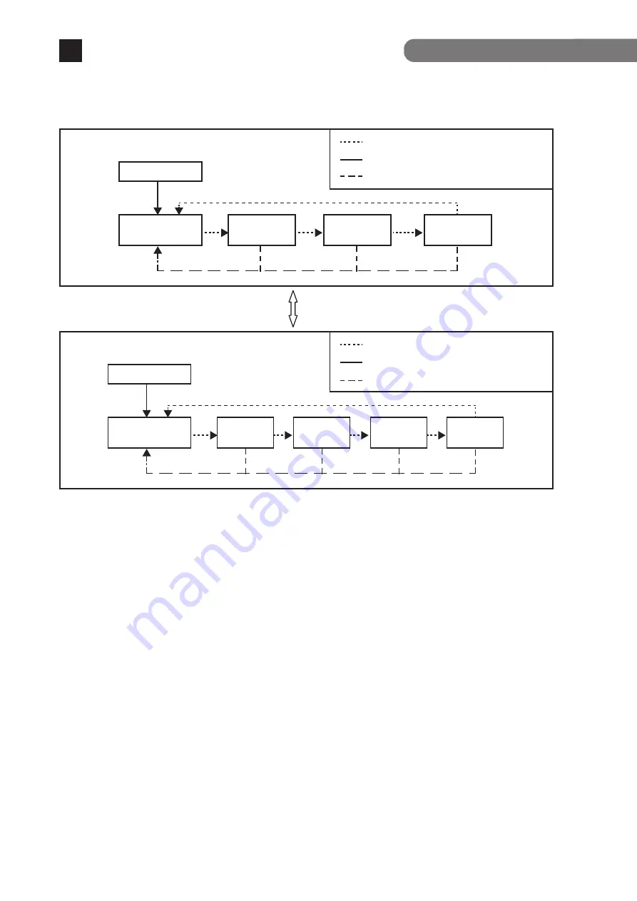
Switch two types of Base modes and their LEDs in the following way:

When Base mode is Status mode (factory default setting)

When Base mode is ECO mode

Switch Base mode (keep pressing "LED DISPLAY 
CHANGE BUTTON" over 3 seconds)

Press "LED DISPLAY CHANGE BUTTON" manually.

Automatic

Automatically returns to Base mode after 1 minute.

Loop detection/shutoff function and loop history function

If you wish to clear loop detection history, turn OFF once the power supply of the
Ethernet Switch and turn it ON again.
Then, loop detection history is deleted.
The Ethernet Switch can hold up to 64 loop history logs.

Boot

Status mode
(Base mode)

GIGA mode

DUPLEX

mode

Loop History

mode

Press "LED DISPLAY CHANGE BUTTON" manually.

Automatic

Automatically returns to Base mode after 1 minute.

Boot

ECO mode

(Base mode)

Status 

mode

GIGA 

mode

DUPLEX 

mode

Loop history 

mode

The Base mode is maintained even after the power is turned OFF.

LED lamps for each mode and LED lamps for ports 1 to 20 correspond as shown in Table 1 (see page 14).

Turns on the port LED with a orange light when a loop occurs in the corresponding port.
The Loop shutoff mode has the following 2 types of modes.
- Block mode (factory default)

When loops are detected, the port statuses are automatically blocked, and just the specified 
packets which include the loop detection packets will be transmitted and received.

- Shut-down mode

When loops are being detected, the ports will be automatically linked down, and none of 
the packets will be transmitted and received.

*Just the loop detection packets from 30 seconds before the set restoration times will 

automatically be transmitted and received.

During loop is occurring, or if loop has occurred within the latest 3 days, LOOP HISTORY 
LED blinks to notify this. It is possible to switch loop detection setting (OFF/ON) by using a 
console cable (for details, see the PDF version of the Operating Instructions). The default 
setting is ON.

CONSOLE

9600.N.8.1(DTE)

SFP▲(19)

SFP▼(20)

SFP▲(17)

SFP▼(18)

LEFT LED(ORANGE):LOOP DETECTION

1

2

3

4

5

6

7

8

9

10

11

12

13

14

15

16

17

18

19

20

Ports 1 to 16 support IEEE802.3at/af PoE. This function allows for power supply of up to 30 W through 
each port and 250W in total through the Ethernet switch.

 PoE power supply function operation overview

2.2 PoE power supply function

Port LEDs (right) 1 to 16

Green Light:  Supplying power normally.
Orange Blink:  Overload caused by a single port. (Requested power is exceeding 30 W. *1) or 

total power supplied by the Ethernet switch.

Off: Not supplying power or no PoE-powered device connected.

PoE LIM. LED (PoE limit)

 For silent fan control high-speed (High)*  For factory default, or low-speed (Low2)

Off: 

Supplying power in the range from 0 to 235 W. 

Green Light:  Supplying power in the range from 235 to 250 W. 
Orange Blink:  A single port's power supply is exceeding the upper limit, or the total power 

supply of the Ethernet switch is exceeding 250 W. 

 For silent fan control low-speed (Low1), or min-speed (Min)

Off: 

Supplying power in the range from 0 to 170 W. 

Green Light:  Supplying power in the range from 170 to 185 W. 
Orange Blink:  A single port's power supply is exceeding the upper limit, or the total power 

supply of the Ethernet switch is exceeding 185 W. 

*1 When configured IEEE802.3at (factory default). Exceeds 15.4 W when configured IEEE802.3af.

When the requested power supply for the Ethernet switch is exceeded and it gets overloaded, the 
power supply to the low priority ports is stopped, and the port LEDs (right) of the ports whose power 
supply have been stopped blink orange.
The priority settings for the power supply can be set and changed from the console, etc.

 Power supply while the PoE LIM. LED is blinking orange 

(overload caused by the total power supplied by the Ethernet switch)

When the power supply which is requested exceeds 30 W via a single port and the port LED (right) 
blinks orange, and the power supply is stopped.
Unplug the port cable which is blinking orange, and check the PoE receiving equipment’s specifications.
Caution: 1)  Some PoE-powered devices may have a large difference in power consumption between 

their maximum power use condition and normal condition. Carefully configure them so 
that the upper limit of power supply will not be exceeded.


2)  If you do not set a priority for power supply or if the same priority is given, note that the 

power supply priority is assigned to the ports in ascending order of the port numbers.


  (If the requested power supply for the device overall is exceeded, then the power supply to 

a port with a higher port number will be stopped first.)

 Power supply while the overload is caused by a single port

* For the configuration and management method, please see the PDF version 

Operating Instructions on Panasonic’s website.

Содержание GA-MLD16TPoE+

Страница 1: ...Ethernet Switch by customers are not covered by the warranty I0522 20822 Printed in Japan GA MLD16TPoE Model No PN261693D NZ The instruction manuals Menu Version CLI Version Web Version latest firmware and SDN application ZEQUO assist Plus can be downloaded from the following URL https panasonic co jp ew pewnw english datadownload index html 2 12 7 Higashi Shimbashi Minato ku Tokyo Japan 105 0021 ...

Страница 2: ...ions 1 3 Accessories 1 4 Basic operation 2 Part Names and Functions 2 1 LED display change 2 2 PoE power supply function 3 Installation and Configuration 3 1 Grounding Cable Connection 3 2 Mounting to rack 3 3 Attaching the power cord 3 4 Configuration of IP address Basic Troubleshooting 3 7 8 8 9 11 11 12 15 17 18 18 19 20 21 23 2 ...

Страница 3: ...ead to fire electric shock and or equipment failure Do not damage the power cord Do not bend too tightly stretch twist bundle with other cord pinch put under a heavy object and or heat it Damaged power cord could lead to fire short and or electric shock Do not unplug nor plug in the power plug with wet hands Deviation could lead to electrical shock and or equipment failure Do not insert or drop fo...

Страница 4: ...ground terminal screw Connect the power cord firmly to the power port Otherwise this might cause electrical shocks and malfunctions Unplug the power cord if the STATUS ECO LED Status ECO mode or FAN LED Fan sensor blinks in orange system fault Deviation such as keep connecting for a long time could lead to fire Handle the Ethernet Switch carefully so that fingers or hands may not be damaged by twi...

Страница 5: ...nication lines Isolate distribution lines and other distribution lines and low current power lines optical fiber cables metallic water conduits and gas conduits etc Noise may be generated in the communication lines which might cause communication glitches Do not connect any other devices except for 10BASE T 100BASE TX 1000BASE T devices to the twisted pair ports Deviation could lead to equipment f...

Страница 6: ... pair cable leading to malfunction If you connect such a device it is strongly recommended that you install a surge protective device SPD on the twisted pair port side of this Ethernet Switch A lightning surge current voltage may be conducted to this Ethernet Switch through the power supply or ground wire connected to the power port leading to malfunction If a lightning surge current voltage may f...

Страница 7: ...e with the specification High humidity Possible spilled liquid water Dusty Possible static charge such as carpet Under direct sunlight Possible condensation High low temperature exceeding the specifications environment Strong vibration and or strong shock Failure to satisfy the conditions above may result in a fire electric shock equipment failure and or malfunction Such events are not covered by ...

Страница 8: ... X default Telnet SSH allows remote configuration changes and verifications of the Ethernet Switch Remotely configure the PoE settings for each port Ports 1 to 16 The connection status for each port is detected by the power saving mode and it can suppress the power consumption to required volumes when not linked up Factory default deactivated Rapid Spanning Tree Protocol is supported allowing to b...

Страница 9: ...ion Link Aggregation IEEE802 3ad Configurable up to 10 groups Max 8 ports per group VLAN IEEE802 1Q tagging VLAN protocol compatible Max 256 groups including the default VLAN Port based VLAN Internet Mansion function QoS IEEE802 1p compatible Supports 8 priority queues Management method ZEQUO assist Plus SNMP v1 v2c v3 Telnet SSH v2 Console WEB control screen Power supply function Ports 1 to 16 su...

Страница 10: ...Switch power will be shut off Others STP RSTP MSTP Supports the IEEE802 1X authentication MAC based port based MAC authentication WEB authentication Triple authentication STEP authentication IEEE802 1X supplicant Port monitoring Ring protocol IGMP snooping Loop detection shutoff function Storm control DSCP mapping function Login RADIUS function DHCP client function PoE scheduler function PoE auto ...

Страница 11: ...e LEDs are turned ON Then POWER LED Power lights in green STATUS ECO LED Status ECO mode lights in orange and self diagnosis of hardware is executed On completion of self diagnosis POWER LED Power STATUS ECO LED Status ECO mode TEMP LED Temperature sensor and FAN LED Fan sensor light in green and the Ethernet Switch starts operation as a Ethernet Switch As this Ethernet Switch succeeds in communic...

Страница 12: ...ng with IEEE802 3at af Devices such as 10 100 1000BASE T terminal hub repeater bridge and Ethernet Switch can be connected to this port Install the device so that the length of twisted pair cable CAT5e or above becomes 100m or less SFP extension slot ports 17 20 Install SFP module It becomes exclusive usage with twisted pair port When SFP extension slot is linked the ports is automatically switche...

Страница 13: ...port s power supply is exceeding the upper limit or the total power supply of the Ethernet Switch is exceeding 185 W TEMP LED Temperature sensor Green Light The system is normally operating Orange Blink The temperature exceeded the set threshold of the internal temperature sensor Set threshold of the internal temperature sensor 62 C factory default FAN Fan sensor LED Green Light The system is norm...

Страница 14: ...cted Green Light Orange Blink Off LOOP HISTORY Green Light Loop has been detected within the last 3 days Off No loop detection history It is shut off via the loop detection and shutoff function storm control or the BPDU guard PoE are being supplied power Power is not being supplied or the PoE receiving equipment are not connected Also it is set in the ECO mode Single port overload Also an overload...

Страница 15: ... release the button the Base mode is changed to the selected mode If the mode is changed to the GIGA mode DUPLEX mode or loop history mode and the LED display switch button is not used for one minute or longer the mode automatically returns to a Base mode Status mode or ECO mode The Base mode is maintained even after the power is turned OFF Indication on the front panel and LED lamps You can displ...

Страница 16: ...ode The Base mode is maintained even after the power is turned OFF LED lamps for each mode and LED lamps for ports 1 to 20 correspond as shown in Table 1 see page 14 Turns on the port LED with a orange light when a loop occurs in the corresponding port The Loop shutoff mode has the following 2 types of modes Block mode factory default When loops are detected the port statuses are automatically blo...

Страница 17: ...EE802 3at factory default Exceeds 15 4 W when configured IEEE802 3af When the requested power supply for the Ethernet switch is exceeded and it gets overloaded the power supply to the low priority ports is stopped and the port LEDs right of the ports whose power supply have been stopped blink orange The priority settings for the power supply can be set and changed from the console etc Power supply...

Страница 18: ... must be no less than 18 AWG and the length is 50 cm 3 The ground installed screw shall comply with 3 5mm minimum in nominal thread diameter and engage at least two complete threads into metal chassis with appropriate fixing hardware like washer 4 The grounding cable shall not be removed during normal operation servicing or maintenance 5 Installation steps Step 1 Ensure the detachable power supply...

Страница 19: ...xing the mount brackets and the Ethernet Switch Fix the mount brackets to the four holes on each side of the Ethernet Switch using the screws Then securely install the Ethernet Switch on the rack using the four provided screws for mounting on a 19 inch rack or screws provided with the rack ...

Страница 20: ...nstallation and Configuration 3 3 Attaching the power cord 3 Insert the supplied power cord into the power port Then hang the power cord on the cord hook block to secure it Power cord hook block Power port ...

Страница 21: ...ng command Screen 3 enable configure config interface vlan 1 config if ip address 192 168 1 254 255 255 255 0 5 Enter the following command to save the setting config if exit config exit copy running config startup config 6 Since the following screen is displayed enter Y and the settings will be saved Screen 4 Confirm that the settings have been normally saved Screen 5 7 After configuring start wi...

Страница 22: ...A MLD16TPoE config interface vlan 1 GA MLD16TPoE config if ip address 192 168 1 254 255 255 255 0 GA MLD16TPoE config if GA MLD16TPoE Product Number PN261693D Firmware Version x x x xx MAC Address 00 50 40 xx xx xx Serial Number xxxxxxxxxxx UserName manager Password GA MLD16TPoE enable GA MLD16TPoE configure GA MLD16TPoE config interface vlan 1 GA MLD16TPoE config if ip address 192 168 1 254 255 2...

Страница 23: ... T 100BASE TX or 1000BASE T standard Auto negotiation may have failed Check the port settings of this Ethernet Switch or the terminal settings Is the correct Port LED display mode selected using the LED display switch button The Port LED left lights in orange Loop is occurring By removing the loop orange LED will be turned off LOOP HISTORY LED Blinks in green This is to notify that there is a port...

Страница 24: ...upply may not be possible depending on the installation environment In such cases use a UTP cable Is a CAT5e or better straight cable RJ45 8 8 used Is the cable connected to the port 1 16 that supports PoE power supply Ensure that either the port alone or the entire equipment is not overloaded Is the Powered Device connected to the port compliant with the IEEE802 3at standard or IEEE802 3af standa...

Отзывы: