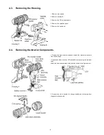
background image

6

3.2.

Trial Operation (after checking Troubleshooting Guide).

3.2.1.

Assembly

• Confirm if there is no gap between housing A, B and C by pinching lead wires.
• There is no dust or deformation on battery terminals.

3.2.2.

Operation

• Check whether the tool operates properly in both the forward and reveres directions.
• Press the light button on the operation panel to confirm that the LED lights up.

• Check whether the tool speed increases continuously as the trigger is gradually engaged.
• Rotate the clutch handle and check whether the clutch switches properly.
• Check if the rotation speed is normal rated value.

High: 1580/min (rpm) at 18V, 1350/min (rpm) at 14.4V
Low: 470/min (rpm) at 18V, 400/min (rpm) at 14.4V

• Pull the trigger all the way back and check whether the tool stops rotating immediately when it is released.
• Set the clutch handle to the [

] mark and check whether the tool rotates without any clutch operation.

• Operate (rotate) the keyless chuck and check whether the chuck's three jaws move smoothly.

3.2.3.

Integrity

• With the switch activated, shake the tool back and forth and up and down and verify that its sound does not change excessively.
• Check for the presence of any dirt or foreign matter from the repair process on the outside of the tool.

Содержание EY74A2

Страница 1: ...law ORDER NO PTD1507X58CE Cordless Drill Driver Model No EY74A2 Europe Oceania TABLE OF CONTENTS PAGE PAGE 1 Warning 2 2 Specifications 2 3 Troubleshooting Guide 3 4 Disassembly and Assembly Instructions 7 5 Wiring Connection Diagram 13 6 Schematic Diagram 13 7 Exploded View and Replacement Parts List 14 ...

Страница 2: ...ing point is 50 70 F 30 40 C higher Please use a soldering iron with temperature control and adjust it to 750 20 F 400 10 C In case of using high temperature soldering iron please be careful not to heat too long Pb free solder will tend to splash when heated too high about 1100 F 600 C 2 Specifications ...

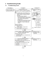
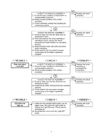
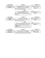
Страница 3: ...3 3 Troubleshooting Guide 3 1 Troubleshooting Guide ...

Страница 4: ...4 ...

Страница 5: ...5 ...

Страница 6: ...er the clutch switches properly Check if the rotation speed is normal rated value High 1580 min rpm at 18V 1350 min rpm at 14 4V Low 470 min rpm at 18V 400 min rpm at 14 4V Pull the trigger all the way back and check whether the tool stops rotating immediately when it is released Set the clutch handle to the mark and check whether the tool rotates without any clutch operation Operate rotate the ke...

Страница 7: ...ning screw inside the chuck clockwise direction and remove the screw in case of the chuck does not come loose NOTE If the chuck fastening screw will not come loose insert the allen wrench into the chuck and lightly tap in the clockwise direction to tighten the chuck and then loosen the chuck fastening screw 2 Insert the allen wrench into the chuck and turn counterclockwise direction with holding t...

Страница 8: ...ion panel 5 Remove the square nut 1 Remove the heat resistant tape and remove the interior components from the housing A Precautions when securing LED assembly in place using the resistant tape Attach the heat resistant tape at the location shown in the figure below 2 Remove the clutch handle H L change handle and click spring from the gear block assembly ...

Страница 9: ...connector 3 Pull the faston terminal directly out from the switch assembly Exercise care not to bend the ter minal fitting 4 Remove the lead wires from the battery terminal Connecting and disconnecting the connector Precautions when attaching the connectors Holding the motor assembly remove the entire motor mounting plate including the gear box assembly from the motor assembly ...

Страница 10: ...te steel balls thrust plate adjust screw clutch spring and thrust plate from the clutch case Assembly precautions 1 Exercise care when attaching the lock ring ring gear stopper and ring gear A to align them in the proper orientation as shown in the above figure 2 When installing the gear case to the clutch case be sure to align the pro truding ribs on the clutch case with the recessed ribs on the ...

Страница 11: ... Assembly and the Clutch Handle 4 9 Assembly of the H L Change Handle Align the gear case assembly s adjusting screw as shown in the figure Position so that the 1 mark on the clutch handle is Aligned with the center of click spring A ...

Страница 12: ...12 4 10 Wiring and Assembly Points ...

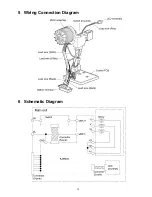
Страница 13: ...13 5 Wiring Connection Diagram 6 Schematic Diagram ...

Страница 14: ...Model No EY74A2 Exploded View ...

Страница 15: ...SEMBLY 1 21 WEY74A2L6768 C RING 1 22 WEY74A2L0857 THRUST PLATE 1 23 WEY74A2S6097 WAVE WASHER 1 24 WEY74A2L0867 THRUST PLATE 1 25 WEY74A2S0647 LOCK RING 1 26 WEY74A2S0207 LOCK PLATE 1 27 WEY74A2S0317 CUSHION PLATE 1 28 WEY74A2S0507 PIN 6 29 WEY74A2S1927 STEEL BALL 12 5 DIA 30 WEY74A2L1647 CARRIER 1 31 WEY74A2L1477 RING GEAR 1 32 WEY74A2S1357 PLANET GEAR 6 33 WEY74A2K0847 THRUST PLATE 1 34 WEY74A2S0...

Отзывы: