background image

ES-RT33/ES-RT53

3

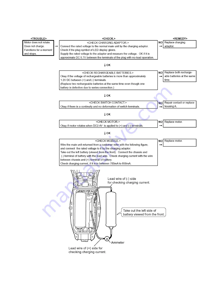
3 Troubleshooting Guide

3.1.

Main unit and charging adaptor

Содержание ES-RT53

Страница 1: ...ng 2 2 Specifications 2 3 Troubleshooting Guide 3 3 1 Main unit and charging adaptor 3 4 Disassembly and Assembly Instructions 4 4 1 Disassembly Instructions 4 4 2 Cautions in Assembly 6 5 Schematic Diagram 8 5 1 ES RT53 8 5 2 ES RT33 8 6 Exploded View and Replacement Parts List 9 6 1 Exploded View for ES RT53 9 6 2 Replacement Parts List 10 6 3 Exploded View for ES RT33 11 6 4 Replacement Parts L...

Страница 2: ...he melting point is 50 70 F 30 40 C higher Please use a soldering iron with temperature control and adjust it to 750 20 F 400 10 C In case of using high temperature solder ing iron please be careful not to heat too long Pb free solder will tend to splash when heated too high about 1100 F 600 C 2 Specifications ...

Страница 3: ...ES RT33 ES RT53 3 3 Troubleshooting Guide 3 1 Main unit and charging adaptor ...

Страница 4: ...you do not replace the trimmer or trimmer handle skip to No 4 Slide the trimmer handle and unhook the trimmer handle by inserting something like a slotted screwdriver or plastic spatula into a slit NOTE In order to prevent the scratch or damage on the housing use the cushion under the screwdriver 3 Loosen a screw and remove the bottom cover 4 To remove the side panels insert a small slotted screw ...

Страница 5: ...e bottom side 7 To remove the trimmer driving bar or the slit blade driving bar press bars outward 8 And take out the battery assembly from housing A 9 Remove the motor assembly and tube holder 10 Remove the battery o ring and washer in each battery Take out the rechargeable batteries from the chassis ...

Страница 6: ...ly 4 2 2 Module Align the projection of switch select button on housing A with the groove of switch plate on module 4 2 3 Rechargeable batteries Insert the rechargeable batteries into chassis Attach the bat tery o ring and washer to the battery Put the battery assembly from the battery terminal side into housing A and insert the motor side into housing A NOTE While setting the battery assembly pul...

Страница 7: ...panel into the housing first Then hook the front side and the rear side of the side panel in order NOTE Make sure that the left and right side panels are firmly fitted on both rear and front side 4 2 6 Trimmer 1 Align the housing with the hooks of trimmer 2 Confirm its operation or smooth movement of trimmer ...

Страница 8: ...8 5 Schematic Diagram 5 1 ES RT53 5 2 ES RT33 ...

Страница 9: ...ES RT33 ES RT53 9 6 Exploded View and Replacement Parts List 6 1 Exploded View for ES RT53 ...

Страница 10: ...3068 HOUSING B 1 16 WESRT53L2128 MODULE 1 17 WES7038L2508 RECHARGEABLE BATTERY 2 Ni Mh Type 2PCS PK 18 WES7025L0976 WASHER O RING SET 2 2PCS PK 19 WESRT53K3368 SIDE PANEL 1 20 WESRT53K1508 TRIMMER 1 21 WESRT53K3848 BOTTOM COVER 1 21 WESRT53K3849 BOTTOM COVER 1 only for CIS 22 WES7023L6058 TAPPING SCREW 9 K2 8 23 WESRT53S3038 BODY BLOCK 1 23 WESRT53S3039 BODY BLOCK 1 only for CIS 24 WESRF41K7664 CH...

Страница 11: ...ES RT33 ES RT53 11 6 3 Exploded View for ES RT33 ...

Страница 12: ...3068 HOUSING B 1 16 WESRT33L2128 MODULE 1 17 WES7038L2508 RECHARGEABLE BATTERY 2 Ni Mh Type 2PCS PK 18 WES7025L0976 WASHER O RING SET 2 2PCS PK 19 WESRT33K3368 SIDE PANEL 1 20 WESRT33K1508 TRIMMER 1 21 WESRT33K3848 BOTTOM COVER 1 21 WESRT33K3849 BOTTOM COVER 1 only for CIS 22 WES7023L6058 TAPPING SCREW 9 K2 8 23 WESRT33S3038 BODY BLOCK 1 23 WESRT33S3039 BODY BLOCK 1 only for CIS 24 WESRF41K7664 CH...

Отзывы: